Hi Bonsai,
Have you published any details on your SOT23 temp sensor? How was it mounted in thermal contact with the relevant semiconductors?
Thanks,
Ian
Hi ihan, take look here page 37 to page 40
http://hifisonix.com/wordpress/wp-content/uploads/2011/03/The_e-Amp_V2.03.pdf
Last edited:
Why? Because they make transistors look bad by comparison?We really shouldn't be discussing tubes in the 21st centuary.🙁
Yes. I did this in real life circa 1990.Has any one tried Transitional Two Pole Compensation.
YES, that is TPC + TMC.
I was hoping to present to yus gurus a SPICE simulation of my Jurassic experiments which started with sorta 'Blameless' and led to 'pure Cherry' and finally Two Pole Cherry
[*] which I gather is your TPC + TMC. It works very well.
The value of the 'opinions' on this thread isn't the theoretical musings .. but the practical tests which have been done to validate these. eg I'm quite happy to accept that various people including Doug & Great Guru Baxandall have had problems getting pure Cherry to work. It's finding out why they had problems when I had a relatively straightforward experience that may add to the store of human knowledge.
Alas, as a beach bum, I can only demonstrate in LTspice what I found in real life. As a SPICE newbie, I'm always suspicious of my results .. especially when they jar with real life experience.
________________
Part of this is finding BJT models I sorta believe. May I ask Mr. Cordell which of the transistors, for which he has reliable models, he would use for TR4 & 6, the VAS & its current source load in Doug's Fig 6.16 (4th ed). Doug uses MPSA06/56 in this simple 50W Blameless.
I have used 2sa970/sc2240 in at least one experimental amp but they are not really ideal (??!!) devices in this position. I'm trying to use reliable models which are as close as possible to what I actually tried circa 1990.
________________
An important reason for favouring pure Cherry and its bastard derivatives like TMC is that Iq, once above a small value like 20mA, is VERY non-critical. This has important implications in production testing. You don't really want to have to set this to a critical value while the amp warms up .. especially if Iq takes a long time to settle.
It also opens up the use of output devices with rotten Gm characteristics like VFETs.
________________
On the subject of theoretical Gain & Phase margins, I suggest that though useful during design, once you start testing the real McCoy with real loads eg 1n - 100n caps, you quickly see they tell only a very limited and often inconsequential part of the story. eg the problems with pure Cherry as seen by Self & Baxandall, appear to be mainly parasitic (Translation: dunno why they happen) and don't appear in the usual naive loop gain plots.
BTW, if you are attempting to simulate stability problems, you definitely need to simulate real leads between PSU & the power amp.
* Just realised what I tried isn't a form of the bastardised TMC. Instead it splits the pure Cherry capacitor and takes the junction to some 'earthy' point (like TPC does with the traditional Miller cap)
BTW, if you are attempting to simulate stability problems, you definitely need to simulate real leads between PSU & the power amp.
I find that, in reality, one of the biggest enemy of a stable amplifier is parasitic inductance on each power rail, including power ground.
In simulation, when you put 1uH in series to each power rail, you will be surprised to see some big parasitic oscillation during square wave test. In some case, it will cause amplifier latch up cause global stable problem. Actually, simulation is more attempt to show oscillation than real test. Because there is no ESR in each CAP, there is no resistance in each wire to damp the oscillation. Proper grounding, separating signal ground & power ground, decoupling power supplier, those technique can effectively get rid of this kind of oscillation.
(1uH is the worst case test. It could be a poor quality 1 meter long copper wire.)
I just recently found some interesting facts. One of them is that, output ground should be taken from some place near amplifier output stage. If you have localized power decouple CAPs for output stage, the output ground should be taken from the common ground of those CAPs. I used to wire output ground directly from PSU ground. In some extreme cases in simulation, it will make amplifier unstable at high frequency (around 1MHz). I am sure a lot of DIYers wiring ground like this.
The idea of localized decouple CAP is that output stage get power from those CAPs instead of PSU. It is very important also to provide a pass for returning current to those CAPs, so the output ground should be taken from the common ground of those CAPs.
That's an example for where reality can be different from simulation.
Last edited:
Why? Because they make transistors look bad by comparison?
Revisionism in electronics..?...😕
Why? Because they make transistors look bad by comparison?
Because they (valves) are absolute rubbish.

Last edited:
Has any one tried Transitional Two Pole Compensation.
YES, that is TPC + TMC.
Actually, they can work at same time.
Can you show a schematic demonstrating this? I doubt if this is stable.
Agreed to most of this good stuff.I find that, in reality, one of the biggest enemy of a stable amplifier is parasitic inductance on each power rail, including power ground.
In simulation, when you put 1uH in series to each power rail, you will be surprised to see some big parasitic oscillation during square wave test. In some case, it will cause amplifier latch up cause global stable problem. Actually, simulation is more attempt to show oscillation than real test. Because there is no ESR in each CAP, there is no resistance in each wire to damp the oscillation. Proper grounding, separating signal ground & power ground, decoupling power supplier, those technique can effectively get rid of this kind of oscillation.
(1uH is the worst case test. It could be a poor quality 1 meter long copper wire.)
I just recently found some interesting facts. One of them is that, output ground should be taken from some place near amplifier output stage. If you have localized power decouple CAPs for output stage, the output ground should be taken from the common ground of those CAPs. I used to wire output ground directly from PSU ground. In some extreme cases in simulation, it will make amplifier unstable at high frequency (around 1MHz). I am sure a lot of DIYers wiring ground like this.
The idea of localized decouple CAP is that output stage get power from those CAPs instead of PSU. It is very important also to provide a pass for returning current to those CAPs, so the output ground should be taken from the common ground of those CAPs.
An important point is that for 1pp zillion THD @ 20kHz and good stability, the important local decoupling caps are the electrolytics. (cos they have built in series resistance) You can add any number of Golden Pinnae decoupling caps but don't neglect the electrolytics which must be AT the output devices / drivers / VAS.
Another reason for avoiding long twisted leads from driver PCB to output devices 😀
A very useful set of hints are Scott Wurcer's recommendations for grounding & decoupling in the AD797 datasheet.
_______________
To return to the original thread ... Mr. Self, could you please expound clearly, in words of one syllable so us unwashed masses are not confounded, your own recommendations on this subject? Loadsa pics please.
It is likely that many (most?) DIY amps do not even approach their potential performance cos this grounding & decoupling black magic is poorly understood 😱 There are many myths circulated by pseudo gurus (da High End designers) on the subject.
Can you show a schematic demonstrating this? I doubt if this is stable.
Transitional Two Pole Compensation.
I haven't simulated this. The value may not be right. 🙂
Attachments
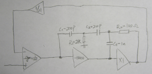
Transitional Two Pole Compensation.
I haven't simulated this. The value may not be right. 🙂
This can't work as you'll have a triple pole roll off of the loop gain. Very unstable.
This can't work as you'll have a triple pole roll off of the loop gain. Very unstable.
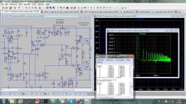
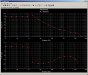
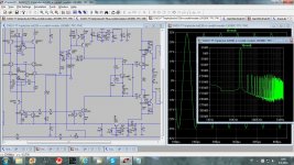
Here is the simulation.
There is plenty phase margin and gain margin. It could be quite stable.
Attachments

Here is the simulation.
How have you simulated the response?
Your circuit shows a probe at the output rather than a loop probe.
Best wishes
David
How have you simulated the response?
Your circuit shows a probe at the output rather than a loop probe.
Best wishes
David
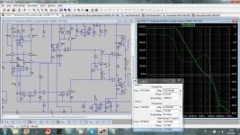
I use Multsim. The graph can be get from "AC Analysis".
In schematic, I use C2 to short the negative input to the ground so that I can get open loop response directly from output. I am not sure how others get open loop response. 😱
How is it called then, lower circuit?
I would call it just voltage loop gain measurement.
I've called the single AC Vsource loop gain test the "Simple Middelbrook" version
I have just realized that the AC Vsource does not actually measure the loop gain.
It measures the Return Difference, as defined by Bode.
Also my earlier post that (de)sensitivity is equal to Return ratio should be corrected to ... equal to Return Difference.
Sorry for the mistake, especially since Bode must have already had this distinction clear in his mind before 1940.
Best wishes
David
I use Multsim.
In schematic, I use C2 to short the negative input to the ground so that I can get open loop response directly from output. I am not sure how others get open loop response. 😱
I am not familiar with Multisim but the problem was just that I missed that C2 was in Farad. Thanks.
Best wishes
David
I've built some conditionally stable circuits with multiple op amps
it is possible to have a region of 3rd order gain slope, as you show - as long as you lower the order, recover some acutal phase margin by the loop gain intercept frequency
but the oppourtunity for weird behavior certainly increases - clipping or even slew rate limiting can give "describing function" large signal oscillations
one of these amps had a large signal self sustaining oscillation mode with a low slew rate precision op amp in the 1st position, but worked fine with a 5x faster slewing fet input op amp even though the GBW of both were very close
I have just realized that the AC Vsource does not actually measure the loop gain.
It measures the Return Difference, as defined by Bode.
Best wishes
David
Loop Gain does not mean Open Loop Gain, it is difference between open loop gain and closed loop gain, or the return difference, yes.
BR Damir
Loop Gain does not mean Open Loop Gain, it is difference between open loop gain and closed loop gain, or the return difference, yes.
Yes, I understand that loop gain does not mean open loop gain.
The point was that Return Difference is not loop gain.
What you have defined is Return Difference.
Loop Gain is Return Ratio = RD - 1.
Not much different for typical audio but it starts to matter when the values are low, usually only near unity crossover frequency.
But this is a critical area for a maximum feedback amplifier and Bode had already realised this and created the two different terms to make it easy to separate the ideas even if the values are similar. Brilliant.
Best wishes
David
- Home
- Amplifiers
- Solid State
- Audio Power Amplifier Design book- Douglas Self wants your opinions