Wouldnt your voltage be 325v?
I thought this was peak voltage input, 230x1.414=325m RMS would be 230?
Yes.
Each voltage source amplitude is peek voltage.
"AC 230 0" is the small signal AC analysis voltage.
Attachments
Validate 6072 SPICE Model
I am trying to use 6072 SPICE model in my circuit. In order to make sure the model is correct, I try to validate the model by the following way.
This is the 6072 SPICE model downloaded from the DiyAudio(it is made by Ayumi Nakabayashi)
*
* Generic triode model: 6072
* Copyright 2003--2008 by Ayumi Nakabayashi, All rights reserved.
* Version 3.10, Generated on Sat Mar 8 22:42:09 2008
* Plate
* | Grid
* | | Cathode
* | | |
.SUBCKT 6072 A G K
BGG GG 0 V=V(G,K)+0.75743218
BM1 M1 0 V=(0.0057774859*(URAMP(V(A,K))+1e-10))^-0.42611934
BM2 M2 0 V=(0.77876794*(URAMP(V(GG)+URAMP(V(A,K))/38.292098)+1e-10))^1.9261193
BP P 0 V=0.00098547839*(URAMP(V(GG)+URAMP(V(A,K))/49.1701)+1e-10)^1.5
BIK IK 0 V=U(V(GG))*V(P)+(1-U(V(GG)))*0.00057643098*V(M1)*V(M2)
BIG IG 0 V=0.0004927392*URAMP(V(G,K))^1.5*(URAMP(V(G,K))/(URAMP(V(A,K))+URAMP(V(G,K)))*1.2+0.4)
BIAK A K I=URAMP(V(IK,IG)-URAMP(V(IK,IG)-(0.00052295488*URAMP(V(A,K))^1.5)))+1e-10*V(A,K)
BIGK G K I=V(IG)
* CAPS
CGA G A 1.4p
CGK G K 1.4p
CAK A K 0.5p
.ENDS
1, I imported the model into the Multisim14 and create a simple circuit to get its Va~Ia Graph

I set the V1 sweeping from 0 to 400V and V2 from 0 to -8V

then using DC-Sweeping to get the Va~Ia Graph

I set the V1 sweeping from 0 to 400V and V2 from 0 to -8V
then using DC-Sweeping to get the Va~Ia Graph
Then I used a software GetData Graph Digitizer to get sample points data
this is the Graph of GE-6072

this is the Graph of 6072 SPICE model

I choose 7 points on -2V line from each Graph for comparision
the plate voltage is around 100,120,140,160,180,200,220
to see the plate current
this is the Graph of GE-6072
this is the Graph of 6072 SPICE model
I choose 7 points on -2V line from each Graph for comparision
the plate voltage is around 100,120,140,160,180,200,220
to see the plate current
The last step seems unnecessary, you could simply overlay the SPICE generated graph over the data sheet to compare the two.
Then I imported two group of date into Excel to see the diffrence

the difrrence of Plate current is +-5%, is the model's accuracy good ?
the difrrence of Plate current is +-5%, is the model's accuracy good ?
Good enough, since the manufacturing tolerance and variations among different makes could easily exceed 5%.
Then I want to use a real circuit to test the model
I used the 6072 in a SRPP circuit

Then I run the simulation of the circuit in Multisim14, and get the voltage(relative to GND) of 4 point


V1=260V,V2=60.956V,V3=57.379V,V4=3.592V
I made a real circuit of it

and get the real voltage of these 4 point

V1=259.8V,V2=142.76V,V3=137.5V,V4=1.932V
the result is quite different from the simulation, especially V2 and V3, the real data is much higher then the simulation one
Is the model correct ?
I used the 6072 in a SRPP circuit
Then I run the simulation of the circuit in Multisim14, and get the voltage(relative to GND) of 4 point
V1=260V,V2=60.956V,V3=57.379V,V4=3.592V
I made a real circuit of it
and get the real voltage of these 4 point
V1=259.8V,V2=142.76V,V3=137.5V,V4=1.932V
the result is quite different from the simulation, especially V2 and V3, the real data is much higher then the simulation one
Is the model correct ?
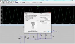
I try to silmulate this SRPP circuit in LT-SPICE

and it is the simulation sets

But it runs too slow after 10 min only finished 0.1%, is tere something wrong with the setting?
and it is the simulation sets
But it runs too slow after 10 min only finished 0.1%, is tere something wrong with the setting?
It looks like you're not feeding any signal to the bottom triode's grid.
Also, you'll want to put a grid leak resistor from the bottom triode's grid to ground.
I've never tried to run an LTspice simulation with a circuit set up like that, so I don't know if what you're doing will run. Try the above and see if you can at least get it to run.
--
Also, you'll want to put a grid leak resistor from the bottom triode's grid to ground.
I've never tried to run an LTspice simulation with a circuit set up like that, so I don't know if what you're doing will run. Try the above and see if you can at least get it to run.
--
Besides, how do you know your tubes meet the specs, did you trace them?
No, I have no equipment to trace tubes. But this is a EH 6072 and I think it's specs should not quite different from GE 6072
It looks like you're not feeding any signal to the bottom triode's grid.
Also, you'll want to put a grid leak resistor from the bottom triode's grid to ground.
I've never tried to run an LTspice simulation with a circuit set up like that, so I don't know if what you're doing will run. Try the above and see if you can at least get it to run.
--
This circuit is part of M10, there is no leak resistor. The circuit can run in Multisim14, why can not run in LT-SPICE?
As rongon replied, you need a signal source and a grid leak resistor for the bottom triode; its grid is floating. Also in Ayumi's 6072 model, you need to change all instances of "^" with "**", minus the quotes.I try to silmulate this SRPP circuit in LT-SPICE
View attachment 641274
and it is the simulation sets
View attachment 641275
But it runs too slow after 10 min only finished 0.1%, is tere something wrong with the setting?
It may be that Multisim places a 1G resistor from all nodes to ground.This circuit is part of M10, there is no leak resistor. The circuit can run in Multisim14, why can not run in LT-SPICE?


Need help: Building 5687 SPICE Model
I have succeed made the 6072 SPICE model, and thanks for the kind-hearted guys helped me with it🙂
and then I want to make 5687 model, because I want to simulate the M10 Preamp circuit. Now I am trying to building this preamp, then I want to use the model to simulate the whole circuit, it will be convinent to use it to adjust the real circuit.
But now I have some difficult with the model.
This is the model that I used Paint_Kit to trace the curve of TUNG-SOL 5687 document
Code:
**** 5687_BIG ******************************************
* Created on 10/21/2017 19:38 using paint_kit.jar 3.0
* [url=http://www.dmitrynizh.com/tubeparams_image.htm]Model Paint Tools: Trace Tube Parameters over Plate Curves, Interactively[/url]
* Plate Curves image file: 5687-big.jpg
* Data source link:
*----------------------------------------------------------------------------------
.SUBCKT 5687 1 2 3 ; Plate Grid Cathode
+ PARAMS: CCG=3.1P  CGP=4P CCP=0.45P RGI=2000
+ MU=18.7 KG1=424.1 KP=82.5 KVB=375 VCT=0 EX=1.29
* Vp_MAX=400 Ip_MAX=50 Vg_step=2 Vg_start=0 Vg_count=6
* Rp=4000 Vg_ac=55 P_max=40 Vg_qui=-48 Vp_qui=300
* X_MIN=50 Y_MIN=50 X_SIZE=1006 Y_SIZE=627 FSZ_X=1696 FSZ_Y=1026 XYGrid=false
* showLoadLine=n showIp=y isDHT=n isPP=n isAsymPP=n showDissipLimit=y
* showIg1=n gridLevel2=n isInputSnapped=n
* XYProjections=n harmonicPlot=n harmonics=y
*----------------------------------------------------------------------------------
E1 7 0 VALUE={V(1,3)/KP*LN(1+EXP(KP*(1/MU+(VCT+V(2,3))/SQRT(KVB+V(1,3)*V(1,3)))))}
RE1 7 0 1G  ; TO AVOID FLOATING NODES
G1 1 3 VALUE={(PWR(V(7),EX)+PWRS(V(7),EX))/KG1}
RCP 1 3 1G   ; TO AVOID FLOATING NODES
C1 2 3 {CCG} ; CATHODE-GRID
C2 2 1 {CGP} ; GRID=PLATE
C3 1 3 {CCP} ; CATHODE-PLATE
D3 5 3 DX ; POSITIVE GRID CURRENT
R1 2 5 {RGI} ; POSITIVE GRID CURRENT
.MODEL DX D(IS=1N RS=1 CJO=10PF TT=1N)
.ENDSThis is the circuit of M10

and this is the voltage that I tested on my real circuit

All the voltage is reference to the GND
and this is the simulation results that I have run in LT-SPICE

the voltage(refrence to GND) of cathode of 5687 is much lower than real one, why?
and this is the voltage that I tested on my real circuit
All the voltage is reference to the GND
and this is the simulation results that I have run in LT-SPICE
the voltage(refrence to GND) of cathode of 5687 is much lower than real one, why?
this is the LT-SPCE file of this circuit, can some one kindly help me to find out the problem?
View attachment 5687.zip
and I have tested all the 5687 models found from this forum, and the result is the same.
View attachment 5687.zip
and I have tested all the 5687 models found from this forum, and the result is the same.
Last edited:
- Home
- Amplifiers
- Tubes / Valves
- Audio Note M10 Clone