I have this audio switch IC - 4 analog inputs to 1 analog output, controllable over I2C.
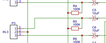
What's weird is on the analog inputs the spec PDF shows a normal load resistor (100K), followed by a 10uF capacitor. Normally for blocking I see the capacitor first, followed by the resistor.
Is this a mistake, or will it work like this too? The outputs from the IC have it the other way, OUTPUT -> CAPACITOR -> RESISTOR TO GROUND, which is how I'm used to seeing it. I'm just curious if it serves some other purpose the way they've done it on the inputs, or if it might be a mistake?
Thanks.
Attachments

The positioning of the blocking caps looks reasonable to me. I believe the idea is support whatever switch channel bias is appropriate; the shunt resistors to ground absorb any stored charge from caps in connected devices.
The AX2358F is single-rail powered, so Vref is not at Gnd level.
As such, both inputs and outputs need a Gnd reference resistor, for input before the cap, and for output after.
So datasheet is correct.
Patrick
As such, both inputs and outputs need a Gnd reference resistor, for input before the cap, and for output after.
So datasheet is correct.
Patrick
Hey Patrick - can you explain what you mean? How does that affect the external resistors to the IC? What Vref do you mean?
https://www.analog.com/en/analog-dialogue/articles/avoiding-op-amp-instability-problems.html
Plenty of info on Google.
But most of it would be inside the chip.
Patrick
Plenty of info on Google.
But most of it would be inside the chip.
Patrick
My question wasn't about an opamp though, it was why the order of the resistor and capacitor was reversed in the schematic. I get how opamp biasing works, but I don't believe those resistors are involved. Which is why I'm not sure I understand what you meant by your response.
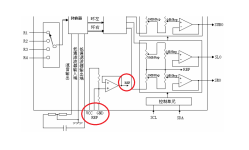
The AX2358 data sheet would be good, but I think it's clear: Audio is a bipolar voltage, so the single supply chip has to have a ~ground voltage called Vref, which is supplied to all the inputs inside the chip, but DC blocking caps are required to avoid shorting those input to the negative power supply. The ~100k resistors on the outside of those caps simply pre-charges those DC blocking caps so that you don't get a Vref spike into whatever you connect to those input and outputs.Hey Patrick - can you explain what you mean? How does that affect the external resistors to the IC? What Vref do you mean?
Unlikely. The IC input impedance is ~33K, so 100K in parallel is not going to make much difference. 100K is a large value to bleed DC and not load the AC circuit.
Attachments
Last edited:
- Home
- Amplifiers
- Solid State
- Audio mixer IC - DC blocking reversed?