As a general guideline: for the specific capacitance and voltage rating you're interested in, look up the ESR of a Panasonic FR (Fox Romeo) capacitor having that capacitance and voltage rating. Panasonic's FR datasheets are very good about showing the ESR. Consider this value to be a maximum-acceptable ESR, and then use any capacitor you like with an ESR less than or equal to the Panasonic FR. Now you can consider price vs performance vs boutique-appeal.
Datasheet attached.
_
Datasheet attached.
_
Attachments

Another thing to consider is how commonly used the capacitor is. Small brands, odd packages & sizes etc will mean this stock has been sitting on the shelf for a long time and has probably deteriorated considerably before you even get your hands on it. So go for the big established brands with constant turnover. And I recommend buying samples and testing them before making a final decision. The datasheets are one thing, but the actual measurements might differ considerably from the datasheet.
I've tested Panasonic FR, Panasonic FM (gold sleeve! woo!), and Nichicon UHD electrolytic capacitors for ESR, using an ET4510 impedance bridge with Kelvin probes (link). In my experience, each of them has a measured ESR as low or lower than the datasheet value.
The same was true for the ULTRA-low ESR polypropylene film "DC link" capacitors from EPCOS, in their "B32653" product line.
The same was true for the ULTRA-low ESR polypropylene film "DC link" capacitors from EPCOS, in their "B32653" product line.
As detailed in post 5, ESR tested at 120 hz doesn't begin to describe the performance of a capacitor in supporting the entire audio frequency range. In particular the vertical edges (drum hits) with components of 15 to 20 khz. There is a reason some manufacturers put low value film caps on the output transistor board. In particular Cs800x, PV-1.3k CS800s have .22 uf film caps inches from the output transistors. Some lines of main size caps may internalize this function. I call 10000 uf rail caps, as do most of us here, but some posters think that size of cap are not rail caps.
Responding to post 20 some 14000 uf caps in a 100 w organ amp with ESR of .35 to .4 on the Peak meter wouldn't deliver even 2 watts.
Responding to post 20 some 14000 uf caps in a 100 w organ amp with ESR of .35 to .4 on the Peak meter wouldn't deliver even 2 watts.
I am sure one could measure rail droop dynamically and make some objective measures.
I have done informal tests addressing this topic and in fact increasing capacitance will decrease droop, up to a point. To increase it further you have to use a bigger transformer.
A very significant (but of course unpublished) difference between a cheap integrated "hi fi" and a decent consumer grade amplifier or receiver is the voltage droop. In fact I observed droops as little as 12% and as high as 70% with steady state test signal. Two units rated "50 watts RMS/channel" will produce very different steady state output. I've seen units that can produce 50 watts unclipped into a dummy load with a transient deliver as little as 12 watts steady state. Others can actually produce their rated power steady state.
So I think it is a topic worthy of further examination.
ET4510 lets you choose one of ninety thousand different test frequencies to do your ESR testing. 10 kHz to 100 kHz, continually variable in 1 Hz increments. It also lets you select the DC bias during the test (1 millivolt steps) and the AC amplitude of the test waveform (1 millivolt steps). This info appears on pdf page 7 of the manual linked in post #23.
Panasonic FR's datasheet tabulated ESR figures are measured at 100 kHz. So are Nichicon UHD's. I verified their numbers by performing my own measurements at 100 kHz.
Panasonic FR's datasheet tabulated ESR figures are measured at 100 kHz. So are Nichicon UHD's. I verified their numbers by performing my own measurements at 100 kHz.
It can be measured easily.I am sure one could measure rail droop dynamically and make some objective measures.
I’m simply baffled how little measurements are provided with almost all PS designs available here. I consider transient response as one of the most critical properties to power supply intended for audio.
Here is an example of transient response to 10A load change at dI/dt that roughly corresponds to 20 kHz. Only 2 mV change at regulator output working at 0.5V drop.
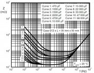
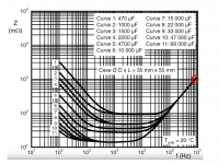
BC Components 056 series datasheet shows the impedance up to 10MHz. This is why i use this type.Panasonic FR's datasheet tabulated ESR figures are measured at 100 kHz. So are Nichicon UHD's. I verified their numbers by performing my own measurements at 100 kHz.
Attachments
Well, those are all big brands, so less of a problem. But I have had problems with EPCOS measuring right at the bottom of the -20% capacitance range. A batch of 10,000uF caps measured closer to 8,200uF. I mentioned this to the supplier and asked them why I never received any of these capacitors on the +20% side. They told me I should buy +/-10% or better if I wanted higher values. So it looks like they are binned in the factory; all the 2nd rate caps are binned into the +/-20%. So if you need 10,000uF then you'd better buy 12,000uF in this tolerance range. I asked this supplier to check their stock for samples in the +20% range, but they never got back to me on this.I've tested Panasonic FR, Panasonic FM (gold sleeve! woo!), and Nichicon UHD electrolytic capacitors for ESR, using an ET4510 impedance bridge with Kelvin probes (link). In my experience, each of them has a measured ESR as low or lower than the datasheet value.
The same was true for the ULTRA-low ESR polypropylene film "DC link" capacitors from EPCOS, in their "B32653" product line.
Why is that a problem? So long as its actually in the range that's all you can expect. +/-20% is fairly tight tolerance for an electrolytic anyway, they can drift more than that as they age whatever the initial value. Sounds like they were well matched in value at least.But I have had problems with EPCOS measuring right at the bottom of the -20% capacitance range
More like 15mF or 22mF - you've not allowed for aging effects. For smaller electrolytics you may as well stick to the E3 values (10, 22, 47, 100,...), for large ones the cost of a larger cap is more of an issue but you can't expect any better behaviour from electrolytics over time, the chemistry is the same. One of the many reasons for using parallel arrays of electrolytics rather than a single big one is that if the odd one starts to fail early the others take over.So if you need 10,000uF then you'd better buy 12,000uF in this tolerance range
I think BC Components might be able to improve their test fixture. It's reporting that every single one of those capacitors has the same impedance at high frequencies. The smallest cap (470uF) and the largest cap (68000uF) both have an impedance of 1000 milliohms at 8 megahertz (red circle). That's an inductance of 20 nanohenries.
L = Z / (2 * pi * f) where Z = 1E0 and f = 8E6
L = 1 / (2 * pi * 8E6) = 2E-8 = 20 nanohenries
_
L = Z / (2 * pi * f) where Z = 1E0 and f = 8E6
L = 1 / (2 * pi * 8E6) = 2E-8 = 20 nanohenries
_
Attachments
As a general guideline: for the specific capacitance and voltage rating you're interested in, look up the ESR of a Panasonic FR (Fox Romeo) capacitor
Thanks Mark for this guideline.
I guess a higher ESR will shorten the capacitors useful life as it will generate more internal heat.
- Home
- Amplifiers
- Solid State
- Audio Grade rail caps vs. datasheet specs