Hello,
I would like to add a volume pot to this amp. Do I take the 150K resistor in red circle out if I am using 100K SMD stepped attenuator or should it stay in?
Thank you
I would like to add a volume pot to this amp. Do I take the 150K resistor in red circle out if I am using 100K SMD stepped attenuator or should it stay in?
Thank you
Attachments
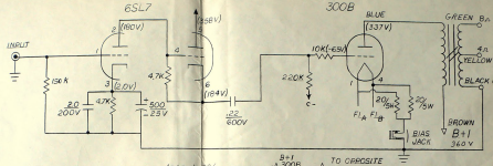
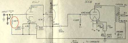
I would replace the 150K with a 1meg in case the wiper of the pot goes open you still have a reference to ground.

stephe,
Thank you for the 1M pointer.
I just got this amp and had to replace the waffle 6SL7 sockets that were falling apart, and looking to improve and make it stable for long term use, do these 2 caps look like they are bulging and about to burst? They do to me...
Thank you for the 1M pointer.
I just got this amp and had to replace the waffle 6SL7 sockets that were falling apart, and looking to improve and make it stable for long term use, do these 2 caps look like they are bulging and about to burst? They do to me...
Attachments
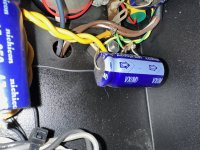
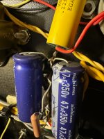
When you replace those bulging caps, try to get 450V rated parts, instead of the 350V rated parts that are in there now. 450V rated electrolytic capacitors are commonly available, your amp's power supply is +360V, and you want the caps you choose to be rated for a higher voltage than they'll ever see in use or in the worst failure mode. It's just a good safety margin kind of thing to do.
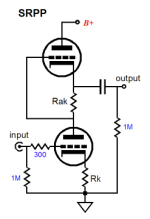
I have a question about this circuit. What is the second half of the 6SL7 doing? It looks like it wants to be a cathode follower, but it doesn't have any load on its cathode before the output coupling cap. What's the design goal for that 2nd stage 6SL7? I'd expect to see a cathode load resistor in the area within the red box, below:

I did that . Thank you !When you replace those bulging caps, try to get 450V rated parts, instead of the 350V rated parts that are in there now. 450V rated electrolytic capacitors are commonly available, your amp's power supply is +360V, and you want the caps you choose to be rated for a higher voltage than they'll ever see in use or in the worst failure mode. It's just a good safety margin kind of thing to do.
Rongon, the way it’s drawn it’s confusing, imo it’s a SRPP circuit , normally it would be drawn with the two triodes on top of each other. In this case they are next to each other and hence it appears it’s missing cathode resistor.I have a question about this circuit. What is the second half of the 6SL7 doing? It looks like it wants to be a cathode follower, but it doesn't have any load on its cathode before the output coupling cap. What's the design goal for that 2nd stage 6SL7? I'd expect to see a cathode load resistor in the area within the red box, below:
View attachment 1439653
I might be wrong, this amp and circuit is new to me.
- Home
- Amplifiers
- Tubes / Valves
- Audio Electronics 300B amp