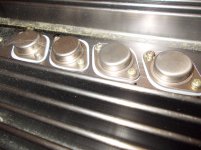
Old Motorola bi-polars as I recall MJ15015 and 15016 come to mind but that is memory at play there. < They could be 2N3055 and 2955 devices also even these old ones are good enough for a 2 times 40 watter amp > All of the mentioned transistors are now obsolete, rare and ungodly priced if original NOS. Most TO-3 are this way currently < obsoleted and very hard to find>
The ones listed below can still be had from ON semi directly or thru distributors.
So a modern replacement set would be MJ15024 and MJ15025, or you could use some older stuff like MJ15003 and MJ15004 which are lower bandwidth stuff they still sell that might just keep the amp stable as replacements will tends to cause the amp section to get awfully unstable. especially when guesstimating upgrade replacements. The 15003 and 4 are the go to for all the 35 year old vintage stuff I see getting rebuilt that was bi-polar class AB, especially McIntosh Vintage.
Hope some of this helps....🙂
Any of these items i can get it. (all ON Semi)
MJ15015/16 3euro/piece
2N3055/2955 1,5euro/piece
MJ15024/25 4euro/piece
MJ15003/4 3,5euro/piece
So, the price does not matter. There is no big difference.
I want "originality" to preserve as much as possible.
Which recommend? MJ15015/16 ?
Thanks
MJ15015/16 3euro/piece
2N3055/2955 1,5euro/piece
MJ15024/25 4euro/piece
MJ15003/4 3,5euro/piece
So, the price does not matter. There is no big difference.
I want "originality" to preserve as much as possible.
Which recommend? MJ15015/16 ?
Thanks
Any of these items i can get it. (all ON Semi)
MJ15015/16 3euro/piece
2N3055/2955 1,5euro/piece
MJ15024/25 4euro/piece
MJ15003/4 3,5euro/piece
So, the price does not matter. There is no big difference.
I want "originality" to preserve as much as possible.
Which recommend? MJ15015/16 ?
Thanks
Any of those listed should work with only concerns being a re-bias of the amp to suit the base drive considerations involved. and some full bandwidth testing < 20 to 20Khz > to verify the base drive actually is correct and the circuitry handles the capacitance variations on the new parts well.
If You could find any of the outputs functional perhaps you could measure their internal capacitance to fit the best possible replacements.
I wish you all the best on this project. They don't build things like this anymore. I know cause I have some early Hafler MOSFET gear like this < hand made and assembled >🙂
- Status
- Not open for further replies.