john curl said:Bob, do you really think that I have made a synthetic 2uH inductor? I feel like the caveman when asked questions by the lady psychriatrist. WHAT?
Hi John,
I think you mis-understood what I was saying. I apologize for the length of my posted question, and realize that it might be easy when skimming it to mis-read what I said.
I certainly was not asking if you deliberately made a synthetic 2 uH inductor to achieve stability. My semantics only meant to mean that the electronics can effectively create an inductive output impedance even when there is no physical inductor present. I know that you are familiar with this concept, and again apologize if my use of the term synthetic did more harm than good.
I was really just trying to get this thread on track and pose some questions which, if you answered them, might really help all of us understand better. I was not trying to give you a hard time or put you in a corner. If anything, I was peacefully trying to throw you a slow pitch. So, I would sincerely appreciate it if you would answer the questions I posed. I and others will truly learn from your answers if you do. Here are the questions from my post above:
Even apart from the question about audibility of it, is the R-L network REALLY needed under reasonable conditions? And what ARE those reasonable conditions? Even if we think we will have to drive a 2 uF electrostatic loudspeaker, does a few feet of ANY speaker cable offer enough isolation to be safe? Maybe. Or are there speaker cables out there with so little leakage inductance and cable resistance that they offer essentially no inherent isolation between the amplifier and a 2 uF capacitive load 6 feet away?
And for similar reasons, is 2 uF of extremely low ESR capacitance right at the output terminals of the amplifier even remotely representative of the worst imaginable real-world load?
Regarding audibility, I'd like to know your opinion on a couple of the issues surrounding the output coil. Let's assume for the moment that we agree that the presence of a certain 2 uH output coil in a certain hypothetical amplifier is indeed audible. If it is audible, why do you think it is audible? Is it audible because of the mere presence of the 2 uH of inductance (even if the inductance were created by an ideal inductor)? Or is it audible because of nonlinear distortions created by the inductor that likely would be measurable (as, for example, by inductor nonlinearity due to proximity to a metal item)?
In other words, is the badness created by the inductance per se, or by the imperfections of the inductor device?
Further to the point, we know that virtually all amplifier outputs are a bit inductive even without the coil. This can be the result of a falling value of NFB at high frequencies or even can occur to some extent in an amplifier without global NFB as a result of the falling beta at high frequencies of an emitter follower output stage. Is such electronically-created inductance OK (not audible), or is it just as BAD as a similar amount of inductance created by an ideal coil?
As an example of inherent "electronic" inductance, if I look at the frequency response of the JC-1 in the Stereophile review for 8 ohm load versus 2-ohm load, it appears that the JC1 may be exhibiting an output inductance as high as 2 uH, even though it does not emply a coil. Do you agree with this estimate of the inherent output inductance of the JC-1?
Thanks in advance for your patience.
Bob
Hi peufeu.
Why Oh Why is there so much unsubstantiated argument throughout this thread when measurement and listening tests have repeatedly been called for ?
Hi Jan,
Here we go again, more condescending nit picking. You cannot deny what your words show !!!
When you make accusations - you attack me as a person !
Now you accuse me of refusing to answer !
Bonsia wrote, and I hope you don't mind me exampling this Bonsia:
>>
I suspect that its not output inductors per se that is causing the difference in sound people claim to hear, but probably the amp misbehaving. And, maybe it sounds better to the listeners ear - but that's a very personal thing because what you deem to sound good might be terrible to my ears <<
>> Graham,
whether the output inductance is in the form of a 2uH coil on the output of the amp, or whether its as a result of the speaker cable, surely the behaviour of the amp output stage is the same? An inductance is an inductance, right?
My point is
1. the output inductance is small compared to the overall inductances connected to the amp output
2. It is likely that other quantifiable variables have a much greater effect on the 'sound' - e.g. speakers - change them and viola - totally different sound. <<
Now all those comments are fair enough Bonsia, but Jan, I wrote the words you are complaining about because Bonsia has mentioned chokes and cable inductance, but not amplifier inductance, which cannot be simplistically added to the former because the former affects the way the loudspeaker is driven wrt the NFB node, whilst amplifier inductance affects the way the NFB output node is itself controlled by the global loop (as Bonsia puts it 'misbehaves').
Jan, yet again I refer you to post 211, plus links to the NFB thread which I have suggested above is where amplifier inductance activity belongs.
Also Jan; I have issues that prevent me from doing what I would like to do, no matter what I would wish for, thus your line of attack is most offensive at a *human* Graham Maynard level.
I am not even in a position to do any audio work for myself at the moment - I have to get someone to do things for me, (have you read/followed the whole thread?) so you ought not think you have the right to EXPECT anything of me in relation to conducting further research !!!!!!!!!!!!
Now please tell me - what concern is it you accuse me of failing to answer now ?
Cheers ........ Graham.
john curl said:Oh, now I have accidently made a 2uH inductor! Wow Far Out! I am just going to have to find out. What do you think that its Q is? Any ideas on the subject?
Hi John,
Is it that you CAN'T answer these very straightforward questions, or that you WON'T answer these questions.
You assert that you want to teach people and share knowledge, then cop out when you have the real opportunity to do so.
Please stop acting like a politician at a debate; we've already got enough of that in our non-audio lives.
Bob
Hi Don,
Was just checking out an inductor value of the sort you describe.
20 to 30 turns at 1" should be in the 5uH to 10uH range.
For a very long time now I have seen folks state that these chokes should be aircore, or they will introduce audible distortion.
If this is the case then their momentary voltage drop must already be significant enough to be audible prior to inducing any saturation point at AF !
I remember D Self illustrating audio frequency cross coupling between spaced L-R channel chokes, so again these chokes must transduce fairly energetic fields. In 1994 I believe he used 6uH but his 2001 text shows 10 turns - circa 2.5uH.
Cheers ........ Graham.
Bob, have you looked at the MEASURED output impedance on the same page? It is 0.06ohms at 20KHz! PLEASE, read first, before making up any new questions.
Hi Bob,
Not only am I surprised at the questions you EXPECT John to answer, you are supposed to be an expert and contributing to this thread.
Then in your next post your manner towards John is so condesending, seemingly personally undermining and unproductive.
It is obvious to me that you are trying to question John about one of his amplifiers.
What specifically has this to do with John's thread ?
Have you investigated output chokes ?
Is there some reference in your own writings you can provide us all with, for I especially would like read it ?
Cheers ........ Graham.
There is a conundrum....
...between those who know, and those who wish to know, and those who wish to explain and justify.
Commercial products use hard won topologies, layouts, dimensioning and component choice. This is proprietary information. Knowing this forum is first stop for many researchers is baulking for an accomplished designer. Why should he impart his secrets? Where is this written in stone?
OTOH, many here are deeply involved hobbyists or academic engineers/scientists and they are well used to vigorous, open debate.
Attacking John (and Graham) for reluctance to give out all their secrets is unjust, particularly on a personal level. He would like to stimulate thought without giving it all away - Graham has a very different POV which many have difficulty understanding, so he is mercilessly attacked. Others here are so clearly opinionated, and elitist, that their antics could only be described as poisonous.
Wise up, guys, I've seen enough - this forum is being trashed.
Hugh
Hi Hugh,
If only ......
Hi teemuk,
After cutting through the noise I now have a chance to come back to your genuinely valid contribution to this thread.
Congratulations for conducting these simulations/measurements.
A single driver tends to load an amplifier more lightly than a resistor of Re value, though a composite loudspeaker with crossover tends to be more reactive with a dynamic loading quite different to its steady sine loading.
Maybe if you tried something like the approximate Ariel equivalent circuit as attached.
I wonder in what way you tried to 'hear' the differences with an electrical model ?
(Genuinely interested here; ie. I'm not trying trick questions or picking holes in your effort.)
You tried a 2uH choke, and say you observed distinctive crossover components.
Did you check their frequency range/spectrum ? ( I would expect these to far exceed AF frequencies. Thus AF digital equipment might have insufficient bandwidth.)
The voltages you measured for a 2uH choke and nominal 4R LS are relatively greater than those I simulated with a suddenly starting at 10kHz with 6uH choke and the virtual 5.3R(complex nom) Ariel LS, a figure which many in this thread (like Jan) have stated their opinion on as my - "your insistence to built a whole framework of bogus theories as based on a single input signal that is irrelevant to audio".
However, using a musical sample can hardly be claimed as being 'irrelevant'.
Excuse - I've lost your post as I fill in this little window.
Was your 2uH paralleled by a resistor ?
Looking forward to your reply in the hope that we can take this investigation beyond what some claim as being theoretically impossible, and thus back-up the subjective claims of those who state they have heard a choke having a fractional degrading effect.
Cheers .......... Graham.
Attachments

I'm closing this thread for a day or so to let you all calm down a little. When it is reopened, ANY sniping will be met with bin time.
Hi Pinkmouse,
Ah, I see you have thought it fit for us to be allowed to communicate again.
Hey there were no bad words, and all positions had been clearly stated, thus I feel it most unfair that you prevented discussion by those who are genuinely trying to make progress.
Everyone has a viewpoint, whether others like it or not, and there cannot be any concensus without thrashing out the details.
I personally would like to re-state from my side of this, that;-
It is not theory I am trying to change, but the way it is being used !
And this is bound to cause heated debate.
____________________________________________________
Back to the thread.
Hi teemuk,
In the last post (four days ago) I commented that the error voltages you measured were relatively greater than those simulated by me.
This is quite logical, because my simulation *merely* suddenly started from zero, and was not an input music voltage waveform driving with respect to an already flowing plus either same polarity or opposing back-EMF/reactively-induced current, due to prior waveform energisation.
I look forwards to you coming back with further input.
-----------------------------------------------------------------------------------
Where filters, loudspeakers and reactive circuits are concerned (including many NFB amplifiers), the waveform voltage 'group delay' becomes modified in time by current flow, and thus any voltage error at t=gd has the potential to be at least twice the difference in amplitude for waveforms superimposed at t=0 and t=gd for any excitation when simplistically viewed at either of these time instants.
Not sure whether I could simulate this, though I'm not free to at this moment anyway.
Cheers ......... Graham.
Hi Graham,
As I pointed out the experiment/test that I conducted was a pretty quick one and therefore I’m not planning to make a project out of presenting it in detail. I feel everyone that is handy with SPICE simulations should be able to conduct a similar one and make up their own mind about it – and perform any further experiments to satisfy their curiosity concerning certain details of circuit behaviour. It seems to me that people attending this thread have way more technical know-how than I have anyways.
I did become curios about the effect of a crossover so I ran some two more simulations using a crude crossover circuit (http://www.danmarx.org/audioinnovation/monitors/crossover.gif - speakers where of course modelled accordingly). I also tried the Stereophile “Kantor” circuit from http://www.stereophile.com/reference/60/. The latter actually tended to produce less error signal than the single driver circuit model (shown at http://www.epanorama.net/documents/audio/speaker_impedance.html... I believe I gave the component values in my first post to this thread). With the crude crossover the error signal amplitude was a bit higher than in the initial experiment and most of the crossover-originated artefacts disappeared. As a side note, the crossover distortion component in error signal seemed to be related to loading of the circuit. There was none with low input signal amplitudes but some when the amplifier was working close to its limits.
In every case, error signal was still highest with transient signal content so no change in that. In my opinion, this isn’t that surprising since the inductor is essentially a low pass filter. Anyway, the circuit used as a load definitely has an effect on how the inductor filter reacts. I suggest trying the concerned experiment also while deliberately overdriving the (simulated) amplifier circuits. I noticed that clipping substantially increases the amplitude of the error signal.
Ltspice allows output plots (V or I / time) to be written into a wave file, which means I can listen to the output of the simulated circuits. The reason why I could not hear any difference might be explained by the fact that even the highest error signal amplitude (which was about 120 mVpeak if my memory serves me right) is still only a tiny fraction of the total output signal amplitude, which during the peaking of the error signal was about 20Vpeak. Any difference in signal is simply too small to be perceived – or at least it is for me.
There was 10-ohm resistor in parallel with the inductor.
As I pointed out the experiment/test that I conducted was a pretty quick one and therefore I’m not planning to make a project out of presenting it in detail. I feel everyone that is handy with SPICE simulations should be able to conduct a similar one and make up their own mind about it – and perform any further experiments to satisfy their curiosity concerning certain details of circuit behaviour. It seems to me that people attending this thread have way more technical know-how than I have anyways.
Maybe if you tried something like the approximate Ariel equivalent circuit as attached.
I did become curios about the effect of a crossover so I ran some two more simulations using a crude crossover circuit (http://www.danmarx.org/audioinnovation/monitors/crossover.gif - speakers where of course modelled accordingly). I also tried the Stereophile “Kantor” circuit from http://www.stereophile.com/reference/60/. The latter actually tended to produce less error signal than the single driver circuit model (shown at http://www.epanorama.net/documents/audio/speaker_impedance.html... I believe I gave the component values in my first post to this thread). With the crude crossover the error signal amplitude was a bit higher than in the initial experiment and most of the crossover-originated artefacts disappeared. As a side note, the crossover distortion component in error signal seemed to be related to loading of the circuit. There was none with low input signal amplitudes but some when the amplifier was working close to its limits.
In every case, error signal was still highest with transient signal content so no change in that. In my opinion, this isn’t that surprising since the inductor is essentially a low pass filter. Anyway, the circuit used as a load definitely has an effect on how the inductor filter reacts. I suggest trying the concerned experiment also while deliberately overdriving the (simulated) amplifier circuits. I noticed that clipping substantially increases the amplitude of the error signal.
I wonder in what way you tried to 'hear' the differences with an electrical model ?
(Genuinely interested here; ie. I'm not trying trick questions or picking holes in your effort.)
Ltspice allows output plots (V or I / time) to be written into a wave file, which means I can listen to the output of the simulated circuits. The reason why I could not hear any difference might be explained by the fact that even the highest error signal amplitude (which was about 120 mVpeak if my memory serves me right) is still only a tiny fraction of the total output signal amplitude, which during the peaking of the error signal was about 20Vpeak. Any difference in signal is simply too small to be perceived – or at least it is for me.
There was 10-ohm resistor in parallel with the inductor.
Bob Cordell said:
Hi John,
<snip>
For example, even apart from the question about audibility of it, is the R-L network REALLY needed under reasonable conditions? And what ARE those reasonable conditions? Even if we think we will have to drive a 2 uF electrostatic loudspeaker, does a few feet of ANY speaker cable offer enough isolation to be safe? Maybe. Or are there speaker cables out there with so little leakage inductance and cable resistance that they offer essentially no inherent isolation between the amplifier and a 2 uF capacitive load 6 feet away?
Yes, there are speaker cables that are very capacitive and look like they have nil inductance... iirc, John Dunlavy patented some?
And for similar reasons, is 2 uF of extremely low ESR capacitance right at the output terminals of the amplifier even remotely representative of the worst imaginable real-world load?
Well, clearly not.
Seems like 100ufd would be worse, for example.
And or some wildly undulating circuit whose phase angle swings rapidly would likely be worse?
<snip>
Thanks,
Bob
But, I dunno. 🙄
As I said before, Curl: troublemaker 😉
_-_-bear
What did he say? I just called Bear, and I still don't know.  Except, that somewhere, somehow, there most probably is a difficult load that can be buffered by using a coil in the output. However, if you are not up to speed, your standard amp will probably oscillate anyway with that difficult load, coil or no coil.
Except, that somewhere, somehow, there most probably is a difficult load that can be buffered by using a coil in the output. However, if you are not up to speed, your standard amp will probably oscillate anyway with that difficult load, coil or no coil.to add to the modeling I've shown Graham's areil circuit, redrawn to show what I believe are the driver's electromechanical motional impedance components grounded as you can see in other dynamic driver models
this should give the electrical analog of cone velocity at the nodes so labeled - another layer of modeling would add mechanical-acoustic coupling to give a predicted spl
I assume that whatever the mechanical-acoustic model that the output spl in a nominally linear system will have approximate proportionality to the cone velocity (at each frequency - kind of the definition of linear system)
the sim steps the L_amp_output from a negligible (and unrealistic) 2 pH to a large by the standards of this discussion 10 uH and the last graph plots the dB difference between the 2 inductor value responses
10 uH is the value at which the difference trace just reaches -40 dB => 1% frequency response difference, and just equal to the threshold established in double blind a/b/x comparison tests as the statistically significant limit of resolution for a wide number of skilled listeners - at least those willing to subject themselves to controlled tests
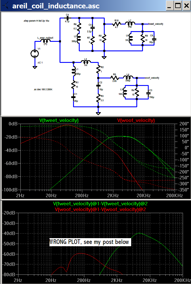
while there is little doubt our understanding of psychoacoustics is incomplete, it would appear that a controlled dbt study showing that the 2 uH output coil that seems be under discussion is audibly detectable with a similar speaker load to the areil model would rate publication
usual Linear Technology SwCAD III aka "LtSpice" file:
this should give the electrical analog of cone velocity at the nodes so labeled - another layer of modeling would add mechanical-acoustic coupling to give a predicted spl
I assume that whatever the mechanical-acoustic model that the output spl in a nominally linear system will have approximate proportionality to the cone velocity (at each frequency - kind of the definition of linear system)
the sim steps the L_amp_output from a negligible (and unrealistic) 2 pH to a large by the standards of this discussion 10 uH and the last graph plots the dB difference between the 2 inductor value responses
10 uH is the value at which the difference trace just reaches -40 dB => 1% frequency response difference, and just equal to the threshold established in double blind a/b/x comparison tests as the statistically significant limit of resolution for a wide number of skilled listeners - at least those willing to subject themselves to controlled tests
while there is little doubt our understanding of psychoacoustics is incomplete, it would appear that a controlled dbt study showing that the 2 uH output coil that seems be under discussion is audibly detectable with a similar speaker load to the areil model would rate publication
usual Linear Technology SwCAD III aka "LtSpice" file:
Attachments
iirc, John Dunlavy patented some?
USP 5,510,578
The number of conductors and the diameter of each conductor is chosen and the design is such that the characteristic impedance of the cable assembly is within the range of the impedance of the loudspeaker.
He forgot that the characteristic impedance of the cable is frequency dependent
I’m wondering why you guys are discussing only series effects of inductor. Why you are not discussing the fact that inductor inside the chassis absorbs all magnetic garbage from power supply loops, etc
dimitri said:I’m wondering why you guys are discussing only series effects of inductor. Why you are not discussing the fact that inductor inside the chassis absorbs all magnetic garbage from power supply loops, etc
Wash, rinse, repeat :
http://www.diyaudio.com/forums/showthread.php?postid=1211264#post1211264
- I'm especially wondering why noone already stuck a network analyzer in there.
john curl said:Continuous sine waves DON'T COUNT!!! Wake up!
Hi John,
I assume you remember some little theorem or other about the equivalence of frequency and time domain representations of linear systems response? - maybe you were one napping?
The DBT test just detectable difference thresholds aren't to my knowledge limited to sine wave tests only - musical signals as well as specially constructed test signals have been explored - and when played back through linear systems with frequency/impulse response characterized by 1% frequency response amplitude matching over our most sensitive hearing region subjects including "golden ears", sound professionals, and musicians, haven't shown statistically significant ability to detect the difference - do have a peer reviewed reference that shows anything else?
All,
apologies, I did mess up the plot and conclusion above
there is in fact an error in my sim presentation, I confused what LtSpice is doing when I subtract dB in the plot display
the correct approach is to plot the ratio of the 2 traces, giving a different result:
3 uH now gives the 0.1 dB, 1% difference with my interpretation of the areil model:
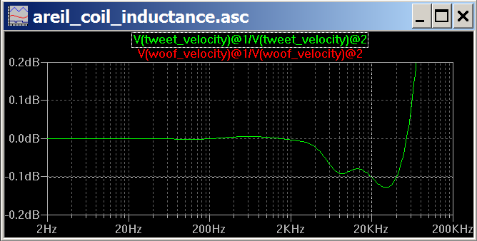
so my final para above is an overstatement;
2uH should be inaudible but is not as far below the threshold as I mistakenly thought
clearly some speaker loads could be worse and would be predicted to be audible by "conventional" psychoacoustic thinking, information on why coils are audible when they don't reach the conventional limits of audibility would be interesting and providing the evidence would be a benefit to our knowledge
Thanks for all your answers and links Teemuk.
It is quite clear why the Kantor 'loudspeaker' circuit induces less choke error - the series resistance is so high as to seriously limit the Q of any series tuned loudspeaker system circuits. Few loudspeakers are like this.
The most obvious series tuned circuit with the Danmarx crossover is 5.6uF~500uH//R+Tw, thus amplifier current here would be ~3.5A for 20V at 4kHz.
Hi John.
Yes sines don't count; sine current through a low value output choke will generate a smoothly alternating and inconsequential field at AF.
_____________________________________________
Personally I think it better to try for audibility with a 5uH series choke. Then when anyone hears a difference they won't even want to bother with a 2uH choke. Whereas, it is possible that equipment could mask 2uH choke degradation and the situation might be misunderstood.
Regarding audibility. I have suggested that the error voltage becomes apparent through the tweeter, as a modulation which makes it sound as if it is reproducing frequencies lower than those of which the crossover network actually passes to it. Listening to the tweeter in isolation produces different treble when driven by different amplifier types, cables etc., and Golden Ears are quite unnecessary. Comments about psychoacoustics are quite un-necessary too.
Hi JCX,
Your traces appear to be sine based; ie. the error you illustrate is steady state reactive.
Maybe you could introduce a dynamic audio waveform.
Cheers .......... Graham.
- Status
- Not open for further replies.
- Home
- Amplifiers
- Solid State
- Audibility of output coils