Both continuous and discrete time transfer functions of nonlinear systems are analysed and inter- preted in the frequency domain by investigating the properties ...
I have never seen anything mentioned about discrete time nonlinear systems as all the theory is in continuous time. The general theory uses convolution of nonlinear impulse responses in multiple dimensions. A second order nonlinearity has two dimensions and a third three, etc. But as you can see this gets to be exceedingly cumbersome for higher orders and as such most investigators simplify the analysis to assuming that the frequency for all of the dimensions is the same, which is a line in any order that can now be far more simply analyzed. But this is applicable only to systems with small nonlinearity. In other words, the simple analysis ignores nonlinear components of the nonlinear components, which is fine for our work. This was all discussed in my paper.
Pete,It takes a lot to drive a compression driver into the ugly area. That being said I am not sure we are gaining much by foregoing true horns which allow the drivers to barely move. There is a purity that is not there in shallow hornguidethingys. And this is where it gets interesting. I contend that we can hear a difference and that difference is due to more or less excursion of the driver. Sometimes lumped into the generic nn linear baskett.
Don't know what you mean by "a lot", but all the HF compression driver specifications and measurements I've seen show considerable distortion at small fractions of their power handling ratings.
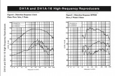
Your contention that "difference is due to more or less excursion of the driver" is not born out by measurement, as you can see in the chart below. The EVDH1A (the lowest distortion HF driver I've found) on a big HP9040 horn has distortion 35 dB below the fundamental at 500 Hz (about 1.78%) but only 15 dB below the fundamental at 15 kHz (about 18%) at just 5 watts, on a driver capable of 75 watts. Obviously, the non linear distortion is not just excursion related.
Art
Attachments
^Above is very interesting. The tests are great.
Getting the crossover/EQ right is more than half the battle. I'm not really sure why this battle is so often lost. 🙁Only when one cleans up the distortions do they start to sound tolerable.
well thing are still "a shakin" here.
to those monitoring this thread i'm interested in feedback and comments to the two articles i linked to in post 349.
to those monitoring this thread i'm interested in feedback and comments to the two articles i linked to in post 349.
Look, things are still "shakin" for the reason they are neither simple nor trivial. You may get simple (and easily understandable) answer to a complex issue, but it would not work.
Pete,
Don't know what you mean by "a lot", but all the HF compression driver specifications and measurements I've seen show considerable distortion at small fractions of their power handling ratings.
Your contention that "difference is due to more or less excursion of the driver" is not born out by measurement, as you can see in the chart below. The EVDH1A (the lowest distortion HF driver I've found) on a big HP9040 horn has distortion 35 dB below the fundamental at 500 Hz (about 1.78%) but only 15 dB below the fundamental at 15 kHz (about 18%) at just 5 watts, on a driver capable of 75 watts. Obviously, the non linear distortion is not just excursion related.
Art
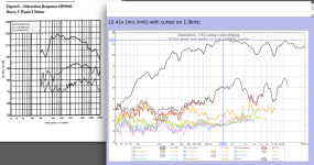
So the distortion test I did for you on the Trynergy with a 10F showing 2% distortion below fundamental at 114dB beats one of the best CD's? There was still room to go on the 10F too. My mic was the limiting factor as it maxes at 115dB. This is at the distortion peak near 2.35kHz. At 500Hz the distortion is lower in the -50dB range, and as you saw increases linearly rather non linearly with SPL.
http://www.diyaudio.com/forums/full...l-range-tractrix-synergy-104.html#post4539890
Last edited:
Getting the crossover/EQ right is more than half the battle. I'm not really sure why this battle is so often lost. 🙁
True, I was referring to the horn part alone, not the system. Crossovers for horns are far more difficult to do and don't fit the classic named filters.
Xrk971,So the distortion test I did for you on the Trynergy with a 10F showing 2% distortion below fundamental at 114dB beats one of the best CD's? There was still room to go on the 10F too. My mic was the limiting factor as it maxes at 115dB. This is at the distortion peak near 2.35kHz. At 500Hz the distortion is lower in the -50dB range, and as you saw increases linearly rather non linearly with SPL.
http://www.diyaudio.com/forums/full...l-range-tractrix-synergy-104.html#post4539890
Assuming your SPL calibration is correct, it appears the Scanspeak 10F/8424-00 driven Trynergy as tested has considerably less THD than the EV DH1A on a HP9040 constant directivity (CD) horn.
The 10F power handling specs use protocols I'm not familiar with (IEC17.1 and 17.3 at 15W and 30W) so hard to say how much "room to go" it has.
The DH1A has an easy 10 dB more dynamic range available from 500 Hz up using a 6 dB crest factor signal, though distortion would also rise considerably.
Although the Trynergy distortion level looks very promising, the polar response above 5kHz is very erratic. The on axis frequency response can be corrected with EQ, but the polar response cannot- linear vs non-linear distortion problems.
Art
Attachments
Despite a little lower BL factor the 10F but in 4 ohms worths maybe a try, his better sensivity may reduce even more the break-up of the cone (responsible of a part of the heared distorsion if not only coming from the horn geometry).
It has also a little less Qts (0.39/0.40)
Off topic, but after all if lower sensivity is enough because the owner have not a SE tube, a little classic FR driver may suffice in a horn in a living room or any home environment.
This idea xrq971 materialized with the Trynergy gave me the envy to try !
It has also a little less Qts (0.39/0.40)
Off topic, but after all if lower sensivity is enough because the owner have not a SE tube, a little classic FR driver may suffice in a horn in a living room or any home environment.
This idea xrq971 materialized with the Trynergy gave me the envy to try !
Xrk971,
Assuming your SPL calibration is correct, it appears the Scanspeak 10F/8424-00 driven Trynergy as tested has considerably less THD than the EV DH1A on a HP9040 constant directivity (CD) horn.
Art
It's hard for me to understand a 20 dB difference in 2nd harmonic at about 1 kHz between the two devices. This is not a small difference and something of note between the two different designs should be apparent. I am not familiar with either design so I have to ask if anyone else can explain it.
It's hard for me to understand a 20 dB difference in 2nd harmonic at about 1 kHz between the two devices. This is not a small difference and something of note between the two different designs should be apparent. I am not familiar with either design so I have to ask if anyone else can explain it.
My thinking is that it comes down to diaphragm or membrane motion. Displacement ties in directly with distortion (more motion, more distortion). How much of the diaphragm motion (in % of xmax) on a compression driver is used to achieve 114dB? xmax (or maybe xmech) on a compression driver, I am told, is circa 1mm before it bumps against the phase plug. On a full range cone driver designed for direct radiator duties, the driver has a lot more motion capability. My simulations show that the horn loading on the cone of the 10F is so efficient, it moves circa 55 micrometers (that is 55/1000 of a mm) to achieve 114dB. That is 2.2% of xmax for the driver - which could be considered the infinitessimal low motion limit and distortions due to non0linearities in suspension, magnetic fields, hysteresis, etc are essentially zero. Another way to look at it is to use a Taylor series approximation of the non-linearities, and in the limit that x tends to zero, the only significant term left is the linear term. 2.2% of xmax, can probably be safely called motion that is tending to zero. This may explain why Art noticed that the distortion was scaling linearly with SPL at these small cone motions.
As a direct radiator, the 10F already is one of the lowest distortion drivers. Now put a horn on it to reduce the motion and it gets better.
Last edited:
The difference in distortion most likely is related to the compression ratio, the cone driver Trynergy has a very low ratio (around 2/1) while the DH1 (or most any HF compression driver) must have nearly an order of magnitude higher compression ratio.It's hard for me to understand a 20 dB difference in 2nd harmonic at about 1 kHz between the two devices. This is not a small difference and something of note between the two different designs should be apparent. I am not familiar with either design so I have to ask if anyone else can explain it.
With the higher compression ratio comes increased HF air-non linearity - HF drivers exceed 160 dB in the phase plug at levels well within thermal limits, increasing HF distortion. The low compression ratio of the Trynergy avoids that problem, and the narrowing HF response makes up (somewhat) for the reduced HF horn loading.
Patent US6320970 - High frequency compression drivers - Google Patents
I have quoted portions of Eugene J. Czerwinski (R.I.P) & Alexander G. Voishvillo's 2001 patent that offer insights (and math) regarding those problems:
"The horn with a phasing plug at its beginning is essentially an acoustical transformer which matches high mechanical impedance of the vibrating diaphragm to the low impedance of open air.
A horn speaker introduces distortions at high output levels which are perceived by a listener as a lack of quality and clarity of sound. The distortions of a horn speaker are caused by several reasons. Distortion may occur due to the high and non-symmetrical mechanical stiffness of the suspension of the diaphragm. This distortion is dependent on the amplitude of the excursion of the diaphragm. Since the amplitude of the excursion increases at lower part of the frequency range of the driver, the level of this distortion also increases at low frequencies. Great deal of distortion is generated in the compression chamber because of the non-linear nature of the compression of air. Strictly speaking, there are two air chambers in a compression driver. The chamber in front of the diaphragm, namely compression chamber, is open into the horn through the orifices in the phasing plug. The chamber behind the diaphragm, called rear chamber or back chamber, is usually sealed. In spite of the similar basic nature of the air compression-related distortion in front and rear chambers, its behavior is different. The air trapped in the back chamber acts merely as a non-linear spring, somewhat similar to the non-symmetrical mechanical suspension of the diaphragm. The air in the front chamber is also non-linearly compressed during the operation of the driver, but since the front compression chamber is open into the horn, the process of compression is more complicated and so is the behavior of the corresponding distortion.
In order to understand the non-linear behavior of air enclosed in a chamber, one may consider that the diaphragm acts as a piston, reciprocating in a cylinder, which is either closed, which is typical for the rear chamber, or has an orifice of an area which is equal to the entrance of the phasing plug (this holds true for the front chamber). For adiabatic change of pressure which occurs in the cylinder, which is a compression chamber, the relationship between the total pressure and volume in the cylinder is expressed by the Boyle's law, (P0+P(t)) (V0−V(t))γ=P0V0=const , where P0 is atmospheric pressure, V0 is the initial volume, P(t) is the instantaneous change of the pressure in the cylinder, V(t) is the change of the volume of the cylinder, and γ=1.4 is the ratio of the specific heat of the air at constant pressure to the specific heat at constant volume. As the cylinder reciprocates with equal displacement on either side of the initial reference position, the minimum and maximum values of the displacement and correspondingly, the volume, cause non-equal changes of pressure around its initial value P0. The positive change of the pressure (this corresponds to decrease of the volume) has higher amplitude than the negative change of the pressure, which corresponds to the increase of the volume. For a sealed cylinder, the volume V is expressed as V(t)=Xd(t)Sd where Xd is the displacement of the cylinder (diaphragm), Sd is the area of the cylinder (diaphragm). For the partly open cylinder, the front chamber, the change of the volume is expressed as V(t)=Xd(t)Sd−Xt(t)St where Xt is the displacement of the air particles at the orifice of the cylinder at the entrance of the phasing plug and St is the area of the orifice. The air in the front chamber is partly compressed and partly displaced into the entrance of the phasing plug to propagate down the horn to be radiated from the mouth of the horn. Input acoustical impedance of the horn with the phasing plug being at the beginning of the horn is frequency-dependent. It is essentially zero at low frequencies, and then it grows with frequency and reaches the constant value Z = ρ c S t ,

where ρ is the air density, c is the speed of sound, and St is the area of the entrances in the phasing plug. At low frequencies the compression chamber is practically open, there is no air compression and no air-related distortion occurs. At higher frequencies the impedance increases and the chamber gets “closed” (not completely though), and the pressure inside the chamber increases. As the compression of the air increases the distortion grows. Therefore, the distortion increases with frequency until the impedance of the horn reaches its maximum constant value. Obviously, the distortion also grows with the increase of pressure in the chamber. The smaller area of the entrances in the phasing plug causes higher pressure in the chamber, and correspondingly, higher level of air compression-related distortion.
The level of air compression distortion in the front chamber is a compromise with the efficiency of the compression driver as well as the level of high frequency signal. The distortion can be minimized by increasing the volume of the front chamber or the area of the openings of the phasing plug. However, the increase of volume always brings the level of high frequency signal down, and the increase of the area of the openings of the phasing plug may decrease the efficiency of the driver.
While a phasing plug is generally essential to the efficiency of a compression driver, a phasing plug is the direct cause of several problems in compression drivers. Since several paths of different length may extend from the outer periphery of the diaphragm to the horn throat, (this is typical for phasing plug placed over the convex surface of a dome diaphragm) by way of the phasing plug, the generated sound wave at the throat of the horn may be distorted due to the phasing problems. Cancellation of acoustical signal at certain frequencies may occur. In addition, since the phasing plug must be located close to the diaphragm (in order to minimize the volume of air in compression chamber) excursions of the diaphragm are limited and reproduction of low frequency signal is compromised because the displacement of the diaphragm increases at low frequencies."
Art
Art
once again very insightful.
this makes me think that there may be some room for experimentation with respect to drivers (direct radiators) on horns.
compression drivers where originally developed in the days where watts where at a premium and efficiency was the goal. perhaps sacrificing efficiency can achieve an audible reduction in distortion.
do you think that with compression drivers anything useful can come from "back chamber" modification?
Last edited:
Like a damped short TL to relieve the pressure and reduce the air compreasion non linearity. There is probably an optimal hybrid of a conventional cone driver with a low compression ratio phase plug in a horn that is more efficient than a direct radiator but with less distortion than a compression driver.
Hi Art
I know all that, I have studied this problem in depth, but the levels that you were showing - 5 watts - seems like it is hardly enough to generate significant air nonlinearity. Especially not 20 db of difference between a 2:1 compression ratio and the typical 10:1.
I know all that, I have studied this problem in depth, but the levels that you were showing - 5 watts - seems like it is hardly enough to generate significant air nonlinearity. Especially not 20 db of difference between a 2:1 compression ratio and the typical 10:1.
Turk,Art
once again very insightful.
this makes me think that there may be some room for experimentation with respect to drivers (direct radiators) on horns.
compression drivers where originally developed in the days where watts where at a premium and efficiency was the goal. perhaps sacrificing efficiency can achieve an audible reduction in distortion.
do you think that with compression drivers anything useful can come from "back chamber" modification?
"Back chamber" modification would be "reactance annulling", and can be useful to extract the most output from a specific horn/driver combination down to Fc.
Sacrificing efficiency definitely can reduce distortion, a horn loaded driver shows more distortion for a given excursion than a front loaded driver, though for a given SPL, the front loaded driver will have more distortion.
Xrk971's Trynergy is an interesting hybrid between horn loading in the 400-4kHz range, and the horn acting more like a narrow waveguide (with poor polar response) above.
Art
Weltersys,
Can this helps to solve the poor polar response above :
A "phase" plug ?
Some horizontals plugs in front of the apex to extend horizontal polar response like in the bi-radial TAD TH4001 ? (could work in a squared tratricx apex ?)
Can this helps to solve the poor polar response above :
A "phase" plug ?
Some horizontals plugs in front of the apex to extend horizontal polar response like in the bi-radial TAD TH4001 ? (could work in a squared tratricx apex ?)
The "full range" driver used in the Trynergy does not have the Bl (magnetic strength) to push HF through a high compression phase plug as used on a typical compression driver, the HF rolloff would be too excessive to equalize enough keep up with the mid-band output.Weltersys,
Can this helps to solve the poor polar response above :
A "phase" plug ?
Some horizontals plugs in front of the apex to extend horizontal polar response like in the bi-radial TAD TH4001 ? (could work in a squared tratricx apex ?)
ok i've been looking through a lot of info on horn design as of late and i still am unclear as to how a horn (of any design) can be truly considered a "linear" device.
is it not a bandpass device that we hope to have linear over the frequency range of interest?
is it not a bandpass device that we hope to have linear over the frequency range of interest?
I hate to be the one that takes dollar signs out of patent grabbing guys but since I have already pissed of big companies like Creative and Intel in the past and escaped with a house to live in, Does it not seem like someone should be producing "semi compression drivers with bespoke rear enclosures for use in horn loaded designs? Seems like Art has already shown proof of concept here?
- Status
- Not open for further replies.
- Home
- Loudspeakers
- Multi-Way
- Audibility of distortion in horns!