This my first time posting here in this section.Ive been working on car audio amplifiers for a while and became interested in switching power supplies.I'm trying to make one from parts from an atx supply.Not for anything specific,just to learn and see if I can accomplish making it work.Even if it works for one minute I'd be happy lol...
I know enough to be dangerous if that gives a clue who your dealing with.
Its being powered off 115vac mains just like a normal atx with a hopefully 14vdc output.
I know I can modify an atx which I've done but I want to build something from scratch persay.
The plan is to use a uc3843 as the driver(controller) or even a tl494 if it would be easier?
A single N channel MOSFET to drive it.I know there various parts in between I'm just trying to understand it enough to give it a shot.
Of course rectifying and etc on secondary side.
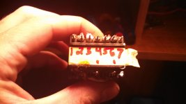
Any advice would be great especially with the pin layout on the following picture.
The primary has 2 pins.One for +dcv and the other is driven by MOSFET.
The secondary has me a little confused.It has 7 pins and I'm struggling a little to determine exactly which is for what.My biggest problem is understand all the pinouts on these transformers.
Once again and advise is appreciated.
I know enough to be dangerous if that gives a clue who your dealing with.
Its being powered off 115vac mains just like a normal atx with a hopefully 14vdc output.
I know I can modify an atx which I've done but I want to build something from scratch persay.
The plan is to use a uc3843 as the driver(controller) or even a tl494 if it would be easier?
A single N channel MOSFET to drive it.I know there various parts in between I'm just trying to understand it enough to give it a shot.
Of course rectifying and etc on secondary side.
Any advice would be great especially with the pin layout on the following picture.
The primary has 2 pins.One for +dcv and the other is driven by MOSFET.
The secondary has me a little confused.It has 7 pins and I'm struggling a little to determine exactly which is for what.My biggest problem is understand all the pinouts on these transformers.
Once again and advise is appreciated.
Attachments
do you have an isolation transformer to use?
threads that exposes members working off the mains is
discouraged here because of safety issues....
threads that exposes members working off the mains is
discouraged here because of safety issues....
I figured this would happen.....Ive worked with 500vdc for years on vfd drives....I'm going to learn and practice regardless....was just hoping for some guidance on design etc
fine, but you must first use an isolation transformer
if you want to continue posting here..there are no two ways about it...
i am sure there will be members who are willing to help you out,
but first things first...here in this board, safety is first...
if you want to continue posting here..there are no two ways about it...
i am sure there will be members who are willing to help you out,
but first things first...here in this board, safety is first...
thanks for understanding.....🙂
your first hurdle is how to dismantle the ferrite cores without breaking them....
your first hurdle is how to dismantle the ferrite cores without breaking them....
That is done by slowly heating the xformer to boiling water temperature. Then it is possible to pull the core halves apart ( use gloves...) but the glue can still be sticky. Some higher quality cores use high temperature glue, so higher temperature might be needed. I have used an oven at 120 C in those cases.
The atx xformers use several windings in series (for 5 and 12V ) aswell as parallel ( for higher current) and sometimes for the negative 12 V.
I suggest you google for ATX transformer , it is difficult to help with just a picture. Plenty of people have done this before 🙂 Also a LCR meter to measure the inductance can be helpful. If possible wind a few turns of wire on the core, measure inductance. Measure all the windings, thus you can calcultae the number of turns. Also, determine how all of them are connected wtih a cennectivity meter is helpful.
Draw them up on a paper so you get an overview.
Second, what voltage are you looking for?
Some cores have so many secondaries that by stacking them in series it is possible to reach 30-40V , at lower current of course.
Third, what topology are you looking at? For me it sounds as you are aiming at a forward converter.
But first, go and get that insulation transformer 🙂
DUTIAI ( Device Under Test Is Always Insulated)
My insulated 800 VA 0-250 VAC Variac is one of the most indispensible tools I have in my possesion.
Last edited:
This link may help you to find out what architecture your atx psu belonged to before you took it apart ... half bridge and forward are the most common and xfrms and rectification differ between these topologies:
AT and ATX PC computer supplies schematics
It is actually not very smart to take these PSUs apart and re-build the whole thing. You will find that you have to put almost everything back in again the way it was.
I usually just modify the secondary part and leave the primary untouched - literally.
It is much easier and safer !
Thanks for the replies.Once again I'm learning this whole smps fiasco! Lol...
I believe the idea was to go with forward converter.Now is forward converter done using the transformer in flyback operation? I'm having trouble finding exactly what forward converter,flyback etc exactly is.Also the output voltage goal was 14 vdc.I know that can be obtained from the supply intact(especially older at's with the 494).Perhaps my idea was foolish?I really want to learn this but there is so much.
Bottom line is I wanted to build a high current supply at the end of the day just to power car audio amplifiers.They are so cheap new perhaps I'll just buy one(won't learn much though).
Lastly,for beginners what would be the easiest(possibly safest) design and voltage to go with.Maybe build a push pull booster that runs off 12vdc?
Beginning by modifying an existing powersupply at the feedback to obtain a slightly higer voltage is done in a day. Redisgning the supply for as you intended takes month.
An basically it will be the same supply. There is a small risk that you cant obtain 14V even if the over voltage protection is disabled in the supply, but any car amp >20W has an internal 12-14V to + - higher voltage converter , and this will certainly work at any voltage >10-11V fees but at reduced output. But worst case you loose (14-12)/14~some 15% output power which is neglible in terms of achievable sound pressure.
So perhaps an unmodifed high power supply ATX 2.x (has most of the power at the 12V rail) will suffice?
Thanks for the reply.I actually several high current supplies for testing amps.The atx mod idea was just for learning purposes.I've modified a couple old at supplies with the 494.
I started reading smps by Keith billings.
To be honest,I don't have to build anything.I just want to learn enough to make one wok that I built.I'm working on a DC DC converter with a small transformer driven by a 3843.
When it doesn't work I'll post on here for help lol.
I started reading smps by Keith billings.
To be honest,I don't have to build anything.I just want to learn enough to make one wok that I built.I'm working on a DC DC converter with a small transformer driven by a 3843.
When it doesn't work I'll post on here for help lol.
- Status
- Not open for further replies.
- Home
- Amplifiers
- Power Supplies
- atx transformer homemade smps