I want to design an attenuator to step down from my modular synth signal level (~+-5V) to line level for input to my mixer. I want to get a quick visual of the level before plugging in to help protect my external mixer. I drew a circuit that seems to be working on the breadboard, but I would appreciate input on whether the audio path design is any good.
A few design choices:

1. Is this set up well for low noise and accurate response for an all-purpose range of sounds?
2. Does this take advantage of the 5532's low-noise design?
3. Is it okay to run the 5532 at 25% gain and do R4+R9 fix the input bias currents?
4. Should I move the pot before the first gain stage to decrease noise?
5. Could I reduce all resistor values to decrease noise?
6. Which capacitors should be polystyrene/etc. for sound quality?
A few design choices:
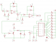
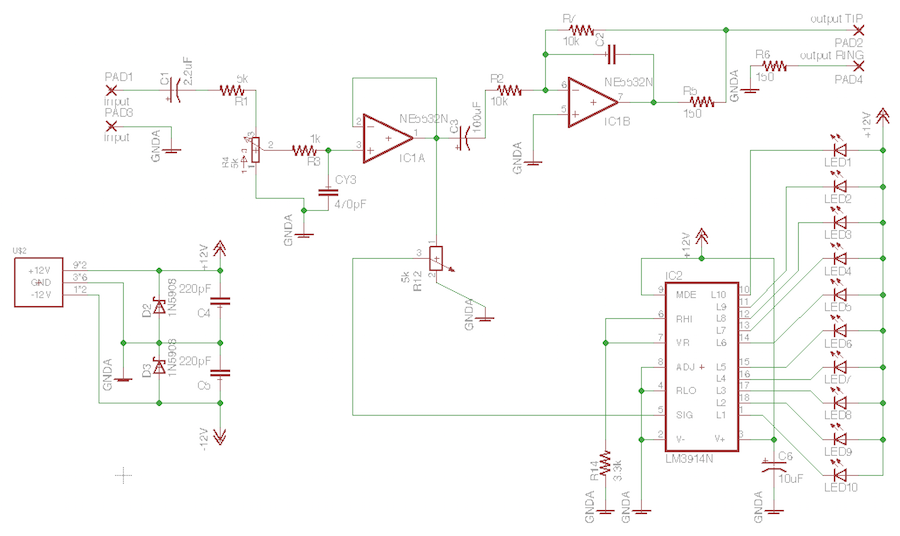
- C1/R1 are intended to block anything below about 10hz.
- Opamp 1 is set up for -25% gain with R4 to fix input bias current.
- CX1&2 are to block above 30khz
- Opamp 2 is set up for -1 gain to correct the phase / R9 for input bias current.
- R15 is there, I assume, to protect the second OpAmp.
- The lower part is all from the LM3915 (mislabeled) datasheet.
- Not shown are two little caps next to the 5532 from ground to each rail.
1. Is this set up well for low noise and accurate response for an all-purpose range of sounds?
2. Does this take advantage of the 5532's low-noise design?
3. Is it okay to run the 5532 at 25% gain and do R4+R9 fix the input bias currents?
4. Should I move the pot before the first gain stage to decrease noise?
5. Could I reduce all resistor values to decrease noise?
6. Which capacitors should be polystyrene/etc. for sound quality?
Attachments
Thanks, Zero D! I imagine that you are not saying to use special caps here then? Regular electrolytics and ceramics?
You could use a polypropylene or polyester for the input cap, a polyester for the filter, & an electrolytic for the output.
Also a variation on the circuit, would be to insert a 6.2k resistor between the output of the input cap & input to the pot. Change the pot to 2k. This would bring the level down to a point where you would be able to have more rotation on the pot before you reached the max level you need.
If this is going to be a stereo circuit, then 1 x 5532 would do it. If it's mono, or you use single OPA's, make sure it/they suitable for a gain of one. You might have to place a small compensation cap between 2 pins. For eg, with 5534's it's pins 1 & 5. Read the datasheets. Ceramic would be fine there.
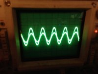
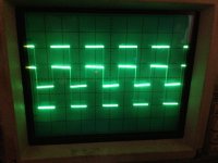
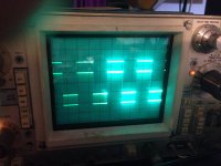
Thanks again, Zero D. I compromised with a 5k input resistor and 5k level pot to max out at 50%. The first attachment is a rectangle wave, which appears to get modified a little at the output - note the sloping down from the peaks. The rectangle is some middle frequency, say 440.
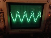
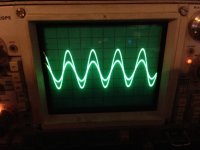
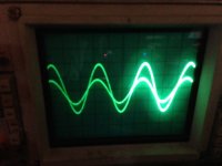
Then I put in four frequencies of sine waves (30, 440, 2000, 10000 -- screenshots attached) and the relationships look good on those.
Then I put in four frequencies of sine waves (30, 440, 2000, 10000 -- screenshots attached) and the relationships look good on those.
Attachments
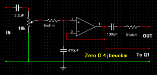
I think the square wave issue "might" be due to the filter. The f3 though is way above the audio range ! I just simmed it without & it's a bit better. Try eliminating the input filter & do this instead, as it also seemed better. Having said that, if it sounds alright, it is alright 😀
Attachments
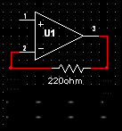
You had 2 input filters, HF & LF. Put the HF back in. Does the output of the circuit you're feeding this have a cap on it, & if so what value ? If it does then i'm guessing it must be higher than 2.2uf, so you won't need the input cap. If it doesn't, then a cap would be sensible, even if the DC offset is low. I simmed with a 10uf - 100uf electrolytic & it seems to sort it. Arrange the polarity of the cap to match the polarity of any DC offest.
Nice scope you got there !
Nice scope you got there !
Photogenic, isn't it? 😉
The synthesizer is made up of a variety of modules, some that will be in development. Part of the reason for this attenuator is to protect the electronics downstream. Any kind of DC offset is possible. I'll see what kind of larger poly caps they have at ABC industrial surplus.
The synthesizer is made up of a variety of modules, some that will be in development. Part of the reason for this attenuator is to protect the electronics downstream. Any kind of DC offset is possible. I'll see what kind of larger poly caps they have at ABC industrial surplus.
The ~10uF range are responding better but I could see going larger. Square wave is still a little tilty coming out.
This has evolved a bit. The peak detector is gone, and I added a balanced output based on the Hinton "best" TRS sender from MUFF WIGGLER :: View topic - Best Jack socket of Bantham 4.4, 1.4 and 3.5 types.
Q: My aluminum panels are connected to GNDA by some of the modules' audio jacks. Does this balanced circuit make sense for me? The "cold" (ring) output is simply shorted to ground with a small resistor. I guess the idea is just to provide a same-impedance clone of the noise signal to be subtracted at the receiver?
Attachments

Do you still need inverter IC1B since your 1st stage no longer inverts?
And if you're blocking DC (a good idea), your always going to have some tilt.
Sonically for the synth sounds, I'm not sure there'd be that much of a noticeable difference going larger than your 2.2uF feeding into 10K of resistance. What is that, a -3dB point of roughly 7Hz? That's lower than any speaker!
what schematics are you using for the modules anyway? i used to mess with diy synth modules many years ago; probably will again with retirement looming within range ....
mlloyd1
Ballpark figure for roofing high-pass (DC-block) is 1Hz cutoff, this means phase error and level droop at 20Hz is very small, even with several places that do the same.
The 10k resistors in the inverter stage can be changed to 2k for small drop in noise if this is an issue (which also justifies C3 being > 15uF!). That 5k on the input is just contributing noise, let the gain pot do that, make it 10k and lose R1. Admittedly the noise of that resistor is being attenuated and most of the time the pot will performing the same function, but when you need the extra gain you'll not be forced to have 5k in series.
You are routing bias current through the pot, so it will be crackly. Perhaps move the input capacitor onto the wiper of the pot and provide a 100k resistor to ground for the bias current of IC1A.
Last edited:
- Home
- Source & Line
- Analog Line Level
- Attenuator design for a modular synth?