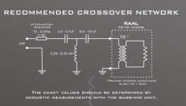
In the specific case of Raal ribbons, if using the xovers recommended by the manufacturer, the question is not to use or avoid using a resistor for attenuation, but where to place this resistor and the right place is BEFORE the xover, and not between the xover and the driver.
The manufacturer actually recommends 4th order LR xover and this is acheived using the primary inductance of the transformer inside the driver. Obviously for this to work you cannot place a resistor before it...😛
The manufacturer actually recommends 4th order LR xover and this is acheived using the primary inductance of the transformer inside the driver. Obviously for this to work you cannot place a resistor before it...😛
Attachments
+2. Many magical differences in subjective evaluations are easily explained by this simple objective aspect.
Dave.
Dave.
distortion = any signal that does not correspond exactly to the input signal or any deviation from the input signal. same idea.
back EMF is a deviation from the input signal, therefore linear or not = distortion.
in this case what is of interest is any current or voltage appearing on the terminals of the speaker, differing from the input, but especially as the result of imperfect mechanical operation, ie. "ringing" and "resonances".
Oh come on, we're talking nonlinear distortion, not linear distortion (and EVERY driver has linear distortion). Linear distortion can be fixed by EQ'ing but non-linear distortion cannot be fixed.
distortion = any signal that does not correspond exactly to the input signal or any deviation from the input signal. same idea.
You may gotta have to understand what you think is same actually it ain't no as same as you think (or thought).
distortion = any signal that does not correspond exactly to the input signal or any deviation from the input signal. same idea.
back EMF is a deviation from the input signal, therefore linear or not = distortion.
in this case what is of interest is any current or voltage appearing on the terminals of the speaker, differing from the input, but especially as the result of imperfect mechanical operation, ie. "ringing" and "resonances".
Back emf is not the result of imperfect operation, quite the other way, it is part of the normal operation of any electric motor, nothing to worry about in itself, independantly of the non linear distortion produced by the driver.
In other words, even with no non linear distortion the driver still produces back emf.
In other words, back emf is not non linear distortion.
Ok, so does this "back EMF" occur at the same time or "in phase" with the input signal?
Or does it occur delayed or "out of phase"?
Or does it occur delayed or "out of phase"?
Isn't a driver's response to a transient assymetry, or resonance for that matter a linear one? What are we talking about, is it a mechanical or motor based non-linearity, is there a variation in driver impedance with cone amplitude through which the source resistance provides a feedback mechanism?Oh come on, we're talking nonlinear distortion,
Ok, so does this "back EMF" occur at the same time or "in phase" with the input signal?
Or does it occur delayed or "out of phase"?
And what s the matter with that? God given is how it fuckin comes!😀
And what s the matter with that? God given is how it fuckin comes!😀
consider making constructive comments?
Look at the impedance curve, which is exactly that complex transfer function of driver voltage to driver current you want to know.Ok, so does this "back EMF" occur at the same time or "in phase" with the input signal?
Or does it occur delayed or "out of phase"?
Hard to decipher what the question actually is (not a native speaker).Isn't a driver's response to a transient assymetry, or resonance for that matter a linear one? What are we talking about, is it a mechanical or motor based non-linearity, is there a variation in driver impedance with cone amplitude through which the source resistance provides a feedback mechanism?
Drive impedance (which actually includes the Rdc of the VC) adjust the internal feedback and thus influences distortion mechanisms.
Think the two extremes :
Force steered (current drive) : All movement is based on pure force injection F(t)= BL * i(t). The voltage that is developed is taken out of the picture completely. The actual cone movement isn't influencing the force in any way in the linear motor region. You can actually block the cone and the force does not change. Zero feedback in the driver.
Damping of the cone movement is only mechanical.
The large signal distortion is governed by BL(x), and Cms(x) at low frequencies. When the BL drops the force is dropping and when Cms increases the force works against stiffer spring, prodicing less excursion.
Pure force injection may cause jump resonance phenomena when there is little external damping.
Velocity conrolled (Rdc close to zero) :
The voltage on the terminals is massively dominated by the microphonic voltage v(t) BL * dx/dt, which is the cone velocity. Any difference between the voltage the amp applies and the voltage that is generated is transferred to a huge corrective current (because of the "zero" Rdc). This is full feedback, you can't block the cone, the current will be increased, and hence the force, until the given velocity is reached again.
Both the force and the micrphonic voltage distortion come from BL(x).
Additionally, the transfer from the voltage difference to the driving current depends on the impedance that couples them which is the static VC impedance Zvc = Rdc(temp)+Le(x), including the distortion that comes with it.
The large signal distortion does have a completely different behaviour that with current drive.
Assume the BL is starting to drop a little. This reduces the velocity signal, the sensor voltage is less than it should be. Immediately the current rises dramatically in order to keep the measured velocity up to requested value. But since the actual velocity is higher than measured by the VC, controling the measured velocity produces too much force injected into the driver, it will overshoot. Also, once the cone has moved away from the correct position it takes a very long time to settle back to the correct position even when the complete drive mechanism wer linear.
Conclusion is : Both true force steered and full velocity controlled operation might not reach the best performance for most drivers (AMT being the exception, they tend to profit from current drive most of the time).
"Best perfomance" of course is somewhat arbitrary. I'm with Earl Geddes here : you want to increase the distortion gradually and you want it to be low order.
And that sweet spot can be externally adjusted to some extent by dialing the proper balance between force steered and velocity controlled operation, and that balance also will vary with frequency. For example we would want the cone motion after any disturbance neither be radically overdamped nor underdamped, best would be aperiodic (Bessel lowpass behaviour of cone transfer function). For ported enclosures we also want the port resonance Q to be in a proper range. This might yield a different drive setup that the one that meets the large signal distortion target.
While with excellent drivers the Rdc may already provide a good overall operating point it is is very likely that it isn't optimal.
What you say seems to make sense..assuming I agree with you..
At any rate, isn't that linear? Maybe the point you're making is about linearising a non-linear motor? If I had to add anything it might be that a good motor used in the right way is a design choice.
Your comments are not specific to ribbons?
You seem to be referring mainly to the system resonance. In the above quote, and in general I suppose we would be interested in any resonance. Is there also the assumption here that overshoot at any frequency would be dissipated at the system resonance the way that the breathing mode of an unbraced cabinet would dissipate wideband excitation into a one note bass?Also, once the cone has moved away from the correct position it takes a very long time to settle back to the correct position even when the complete drive mechanism wer linear.
At any rate, isn't that linear? Maybe the point you're making is about linearising a non-linear motor? If I had to add anything it might be that a good motor used in the right way is a design choice.
Your comments are not specific to ribbons?
Hard to decipher what the question actually is (not a native speaker).
<snip>
And that sweet spot can be externally adjusted to some extent by dialing the proper balance between force steered and velocity controlled operation, and that balance also will vary with frequency. For example we would want the cone motion after any disturbance neither be radically overdamped nor underdamped, best would be aperiodic (Bessel lowpass behaviour of cone transfer function). For ported enclosures we also want the port resonance Q to be in a proper range. This might yield a different drive setup that the one that meets the large signal distortion target.
While with excellent drivers the Rdc may already provide a good overall operating point it is is very likely that it isn't optimal.
So, IF it were possible then "super ultra maximum 'damped'" would be no good?? As in a perfectly "servo" feedback driver, one where all the excess energy/ringing was eliminated??
Sounds like you are advocating a type of 'non-irritating' distortion??
I'm ok with nicer sounding distortion, given the choice between that and not so nice sounding distortion.
I can see how a pure current drive amplifier with a low output Z might be a good way to go, but not how a resistor in series achieves that same result
Well, I'm talking about the settling time of the cone movement to an "external" push event (be it truly external, like forcing the cone manually, or be it coming from an offset of the cone position from a distortion event). When extremely overdamped it takes much longer until the cone is back at its intended position. With normal damping the settling time is determined by the settling time of the system's low-pass behaviour of cone excursion. Say if we have an Bessel alignement (Bessel highpass) of a sealed box, the cone excursion is also Bessel (the double integration does not change the Q). This settling time of the cone to external and distortion events does not change even when we EQ the driver to a different alignment, say via a Linkwitz-tranform to a Butterworth behaviour at a lower cutoff frequency.You seem to be referring mainly to the system resonance. In the above quote, and in general I suppose we would be interested in any resonance
On the other hand, when highly underdamped (resonant, system Q >> 0.7) with pure current drive the cone will ring after any external or distortion-induced offset, again even when EQ'd to a different acoustical target.
It is all very complex with many variables involved so the only way to find whether a driver in a certain application will actually benefit from another damping than that given by its Rdc is to measure it.
Yes, we went off topic to effects most prominent in cone drivers. True ribbons (not AMTs) don't suffer much from back-EMF induced additional distortion, I would suspect (speculation, never had a chance to deal with them, though the RAAL drivers look extremey interesting and have a good reputation). With AMTs it strongly depends on construction, notably the homogenity of the magnetic field and details how the exact geometry of the pleats looks like.Your comments are not specific to ribbons?
Last edited:
You can hook up an amp with negative output resistance slightly less than Rdc, so that the effectiv Rdc is something like 1/10 the original value and study the behavior. I did. As long as you stay well within the linear region (say, no more than 1/10 of its rated Xmax) this actually is working, the driver is doing its own servo control. But when the nonlinearity of the motor kicks in things fall apart quickly, the driver will de-center heavily.So, IF it were possible then "super ultra maximum 'damped'" would be no good?? As in a perfectly "servo" feedback driver, one where all the excess energy/ringing was eliminated??
With true servo control (separate sensor) its all different, everthing depends on the linearity of the sensor but you have to provide means to avoid overexcursion and you must shape the distortion/overdrive characteristic, otherwise the control loop will go open. Very similar to the behavior of an amp with global feedback vs one without.
Er, current drive means high-Z, not low-Z.I can see how a pure current drive amplifier with a low output Z might be a good way to go, but not how a resistor in series achieves that same result
The driver cannot tell apart if its a real resistor of, say, 10 Ohms or a simulated one from an amp with the feedback network set up to give an output impedance of 10 Ohms.
Interesting.
Would the settling behavior (say from a pulse) of a driver that is driven from a "high Z" be governed primarily by the mechanical suspension?
Would the settling behavior (say from a pulse) of a driver that is driven from a "high Z" be governed primarily by the mechanical suspension?
I wouldn't call these the same. In the former case, an example being a driver with a low Q, this damping level being just a point on a continuum for an ordinary linear resonant system. The low Q being suitable in practice for horn systems due to the overall mechanical damping inferred.So, IF it were possible then "super ultra maximum 'damped'" would be no good?? As in a perfectly "servo" feedback driver, one where all the excess energy/ringing was eliminated??
The servo feedback might be more like a Linkwitz transform, or attempted removal of the resonant behaviour by calculated opposition in the drive signal.
I might be missing something here. I tend to see a finite source resistance as a point on a continuum between Voltage and current drive.I can see how a pure current drive amplifier with a low output Z might be a good way to go, but not how a resistor in series achieves that same result
Yes, and that's why it is not very useful down low at the high impedance peak(s).Would the settling behavior (say from a pulse) of a driver that is driven from a "high Z" be governed primarily by the mechanical suspension?
- Status
- Not open for further replies.
- Home
- Loudspeakers
- Multi-Way
- Attenuating ribbons without using resistor