You would be far better of to take the signal source before it enters first classD amp.Thank-you for explaining the concern better than I could.
I still do not understand what are you trying to achieve, if just mix many signals, or individually select...why classD as signal source, why not just operational amp or simple buffer. Since i do not understand the purpose, i can not help anymore. Cheers.
The purpose is to listen to muliple sources of audio. Once the sources are in the digital domain, they can be selected/deselected, mixed, manipulated, etc. indefinitely via VST plugins. Then output for listening. The souce is a Class D amplifier because that is the form factor it is commecially available in. The source normally drives small speakers (e.g., mobile phone size). My goal is to listen via headphones instead and be able to manipulate the sounds as desired. As I already have the source and sound cards, I'm simply trying to find the best way to send the sources' signals from amplifier to sound card. Thank-you for your input and Cheers!
Line level input into it, rather the output.
This is getting weirder by the minute.

The source is a very small multilayered SMD PCB and it is not possible to tap into the audio signal before the Class D amplication stage. As I don't have the time or money to fly all over the US to create the same sound files, the only alterative is not to listen!I don’t understand either. Guess OP has his reasons.
Not possible with a multilayered PCB. I had already considered this.You would be far better of to take the signal source before it enters first classD amp.
Thanks for the links. I haven't seen the specs for these exact transformers, but they tend to have very poor performance in bass frequencies. To preserve them, something along the lines of Jensen audio transformer may be required. That is when 40 channels become cost prohibitive. The goal is to preserve the source signal down to 12 Hz as reasonably as possible. The bass frequencies could be boosted in the VST, but I'm trying to avoid that if possible.10 transformers are fairly inexpensive https://www.aliexpress.com/item/32827431499.html no idea if the frequency response is any good. Ask around maybe somebody here has measured them.
I don't think they are as removing the sound card cover did not reveal transformers on each channel. Also doubt they are decoupled optically. The sound card has 120VAC power supply while the Class D amplifiers have 12VDC power supply. Does that change anything?I’d say it’s pretty unlikely the inputs of the sound card are transformer coupled. So if output of class D needs to be floating or connected with care… not good.
Would it still be a problem when the large current is being shunted through the load resistors and the rest is running through 1k+ of resistance on its way to ground and eventually the other channel? I don't have enough breadth of experience to say if this would still be a problem for some class D designs. Perhaps @loddie could construct a circuit diagram and run it by the mfr. and see if they forsee any concerns, if they're unwilling to divulge any details otherwiseSome classD amps can not have negative signal connected to ground.
Some can not have two negative speaker outputs, like left and right connected to each other.
This may present problem when all plugged into the same soundard with only one ground.
Those isolation transformers may be a necessity.
Great idea. Thank-you, I had not thought of that. I'll work on that now.Perhaps @loddie could construct a circuit diagram and run it by the mfr. and see if they forsee any concerns, if they're unwilling to divulge any details otherwise
When i accidentally shorted left and right negative of speaker output, the amp shuts down. Outputs are floating grounds and can not be connected. I suppose it depends on the construction of the chip, but most are floating.Would it still be a problem when the large current is being shunted through the load resistors and the rest is running through 1k+ of resistance on its way to ground and eventually the other channel? I don't have enough breadth of experience to say if this would still be a problem for some class D designs. Perhaps @loddie could construct a circuit diagram and run it by the mfr. and see if they forsee any concerns, if they're unwilling to divulge any details otherwise
Edited first post as I forgot to mention that the Motu can receive a balanced (1/4" TRS plug) or unbalanced signal (1/4" TS plug). Not sure if that really matters or not.
Yes, I was thinking there will be resistors in series with the negative line too in whatever attenuator he builds to avoid having any shorts between lines.When i accidentally shorted left and right negative of speaker output, the amp shuts down. Outputs are floating grounds and can not be connected. I suppose it depends on the construction of the chip, but most are floating.
Best to use balanced inputs. Do you know input impedance? I know you don't have many specs on unit.Edited first post as I forgot to mention that the Motu can receive a balanced (1/4" TRS plug) or unbalanced signal (1/4" TS plug). Not sure if that really matters or not.
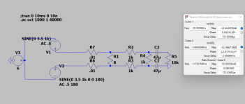
I made this circuit earlier before you said the unit had balanced inputs, so it's a single ended output. 12.5dB attenuation at most AF, -.15dB at 20hz, -.4dB at 12 hz. R1 is load resistor, R2, R3, R4 are the attenuation resistors, R5 is input impedance. Caps remove DC offset. I assumed 6V virtual ground on class D amp output but it doesn't affect anything to change that voltage (once the DC offset is removed). 3W at 8 ohms is 16dbu so this attenuates to 3.5dbu.
Attachments
Last edited:
Unfortunately I don't. The German PDF does not specify it not does the manual for the MOTU 24I sound card which is of the same series/vintage. In my email to MOTU, I did request the input impedance - perhaps they will provide.Do you know input impedance? I know you don't have many specs on unit.
Is this something I can measure? With MM, REW, or other? I haven't found anything online yet one how to measure a sound card's input impedance (again, forgive my lack of knowledge).
Thank-you dkFan9! The FR is very good as there is very little roll off compared to an audio transformer. BTW, the sound card accepts either balanced or unbalanced inputs, so the unbalanced circuit is still compatible. Is it much effort to adapt the design to balanced? I think I have all of these components on hand, so I'll try to assemble a breadboard tomorrow to test.I made this circuit earlier before you said the unit had balanced inputs, so it's a single ended output. 12.5dB attenuation at most AF, -.15dB at 20hz, -.4dB at 12 hz. R1 is load resistor, R2, R3, R4 are the attenuation resistors, R5 is input impedance. Caps remove DC offset. I assumed 6V virtual ground on class D amp output but it doesn't affect anything to change that voltage (once the DC offset is removed). 3W at 8 ohms is 16dbu so this attenuates to 3.5dbu.
This is the general method: http://physics.bu.edu/adlab_and_elab/input-and-output-impedance/Unfortunately I don't. The German PDF does not specify it not does the manual for the MOTU 24I sound card which is of the same series/vintage. In my email to MOTU, I did request the input impedance - perhaps they will provide.
Is this something I can measure? With MM, REW, or other? I haven't found anything online yet one how to measure a sound card's input impedance (again, forgive my lack of knowledge).
You could do it as a loopback. Depending on your multimeter, you could just do 60hz.
Last edited:
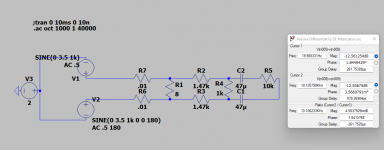
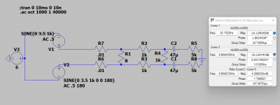
Thinking about it, I'm not sure what you should tie the ground pin to on the TRS on the source end if you go balanced, but frequency response in theory improves. Just increase R2 & R3 to 1.47K (put a 470 in series with 1k) for same attenuation. Leaving at 1k will work, just with 2.5dB or so less attenuation. Changes to input impedance will change attenuation.Thank-you dkFan9! The FR is very good as there is very little roll off compared to an audio transformer. BTW, the sound card accepts either balanced or unbalanced inputs, so the unbalanced circuit is still compatible. Is it much effort to adapt the design to balanced? I think I have all of these components on hand, so I'll try to assemble a breadboard tomorrow to test.
Attachments
Thank-you, that is great link and clever method. I spent about an hour looking and hadn't found anything close yet.This is the general method: http://physics.bu.edu/adlab_and_elab/input-and-output-impedance/
You could do it as a loopback. Depending on your multimeter, you could just do 60hz.
To generate the AC signal, does the source matter? I have a Fluke Pro3000 Toner which generates a 1 kHz continous signal. As long as the test resistor has enough resistance to keep the sound card load/input less than 1V, it seems the toner could be the power source.
My multimeter is a Fluke 77 III and I don't think it has the function needed to generate the AC signal.
Yes that would work. By depending on your multimeter I meant what frequency it could accurately measure. Looks like your meter can measure 1kHz at the 32V and higher ranges which should provide enough resolution to get you close.Thank-you, that is great link and clever method. I spent about an hour looking and hadn't found anything close yet.
To generate the AC signal, does the source matter? I have a Fluke Pro3000 Toner which generates a 1 kHz continous signal. As long as the test resistor has enough resistance to keep the sound card load/input less than 1V, it seems the toner could be the power source.
My multimeter is a Fluke 77 III and I don't think it has the function needed to generate the AC signal.
Thank-you! I will try the second balanced circuit as I should have the extra resistors for it. Yes, I was wondering what to do with ground on the source end as well. Tomorrow, I'll see what I can find.Thinking about it, I'm not sure what you should tie the ground pin to on the TRS on the source end if you go balanced, but frequency response in theory improves. Just increase R2 & R3 to 1.47K (put a 470 in series with 1k) for same attenuation. Leaving at 1k will work, just with 2.5dB or so less attenuation. Changes to input impedance will change attenuation.
Thank-you for confirming! Glad I kept the tone generator as I don't remember even using it.Yes that would work. By depending on your multimeter I meant what frequency it could accurately measure. Looks like your meter can measure 1kHz at the 32V and higher ranges which should provide enough resolution to get you close.
- Home
- Design & Build
- Construction Tips
- Attentuation circuit