We need counterweights to all the EEs around here and their 'good engineering' (Actually I'm an EE too, but completely amateur in this field).
Well, I am an EE too, but I have been building tube amps for about twice as long as I have been building high tech RF communications transceivers. I have been told here several times that you can not use a triode to drive a Schaded pentode. Yet, I have built more than one triode - driving pentode - Schade amps that sounded very nice. I have also built a few that sucked too. The theory does point to the fact that it won't work, but tubes can't read the theory books. My usual method is to build it and see. I can say that some tinkering may be needed to get the desired result, and some combinations just don't work. I have never tried the 12AX7 - 6L6GC, but I think that it would be very doable with a mosfet and some resistors in between the two tubes.
There is at least one member here that insists that a 12AT7 will sound horrible in a SE amp. There are a lot of Simple SE builders that have a different opinion.
My experience with LT spice is that it is usually a good predictor of impending circuit failure. IE, if LT spice says it won't work, it probably won't. LT spice does not predict success, or the level of success too well, since many of the tube models we have are not the greatest. The models don't seem to work well at all when you go far from the expected norm. Positive G1 voltage will usually not work well in LT spice.
Amadeus,
Thanks for the great post. Have you done a sweep to see if the HF response has been affected by using a low current driver ?
Thanks for the great post. Have you done a sweep to see if the HF response has been affected by using a low current driver ?
I find it interesting to get both ends of the spectrum - and both are valid under different circumstances.
The "i don't know much but I like what I hear" approach at one end of the continuum is fine with me as long as its recognised that there MAY be potential for a circuit or device to perform better.
The "I have studied and tested to the nth degree and I can tell you this is THE ducks nuts" is also fine as long as it allows that, for some of us, close enough with available stuff or prefered items is good too.
So, good luck AM - I hope you are enjoying the sound that you have created using the technology and components that match your wants. And with all that landsscaping ahead, you may want to build some outdoor speakers....
OK,
You can use a triode with current-feedback(unbypassed cathode resistor) to drive a Schaded 6L6. But only on the condition that you accept a tenfold higher THD than when driven by a suitable pentode/cascode/MOSFET. You can fool some triodes to do better but its far simpler to go for the other drivers.
When using current feedback on a triode its characteristics goes towards pentode!
Using a lowcurrent triode-driver also forces you to reduce the Schade feedback grossly to even make it work. Results in hi Zout.
We must also remember that whatever topology we choose, distortion-cancellation is the great helper!
The truth is, in my experience, that schade feedback does amazing job of making most combinations work well. Its just great. I have a little headphone amp made from PP ECL82's which uses a triode as driver - it works very well and is a great sounding amp - so obviously it can be done.
However i still ,maintain that a pentode is the simplest method of optimising this circuit, and I think this discussion supports my position.
Shoog
However i still ,maintain that a pentode is the simplest method of optimising this circuit, and I think this discussion supports my position.
Shoog
I have no opinion on the triode v.s. pentode driver question in large part due to lack of knowledge. I am hoping to reduce my ignorance here. When using Schade the feedback imposes linearity on the output tube giving it more triode like characteristics right? As I understand it the feedback acts only on the output tube and has no effect on the distortion spectrum of the driver itself. Is that correct?
I understand that the overall level of distortion (and hopefully the distortion spectrum) is better using a pentode driver. Is this because the improvement in the distortion spectrum of the output tube is far greater than the smaller negative contribution of the pentode driver or is the distortion of the driver somehow improved or cancelled in this circuit?
I presume that it is still pretty important to optimize the plate load on the driver for minimal high order distortion given that the voltage swing is bound to be pretty large.
Any help in understanding the issues is appreciated as I am contemplating a PP 6BQ5 project and partial feedback is a possible option (as is simple UL without FB).
Schade himself mentioned that this would work with triodes and the cult following that the RH84 has built up is a testament to that.
Yes, RH84 is one truly exceptional example of Schade gone bad.
Worst tube amplifier I've ever heard! And was recruited to fix it.
But the worst problem actually turned out not to be the triode.
After a day of making sure the builder (Zobsky) had not deviated
from the RH84 plan, had no bad parts, and hadn't wired anything
incorrectly. I come to conclusion RH84's feedback design is flawed,
especially when G1 starts to forward conduct, even more so than
any worry about the Triode's variable plate resistance.
I fixed one channel by throwing sand at it, and most probs went
away. I don't know if Zob ever followed up to mod his other RH84
channel the same? Even if it sounded great in A2, I think Zob was
not terribly enthusiastic bout adding solid state as a crutch.
Last edited:
As I understand it the feedback acts only on the output tube and has no effect on the distortion spectrum of the driver itself. Is that correct?
This is the way Schade intended it to work, and in most cases this is true.
I understand that the overall level of distortion (and hopefully the distortion spectrum) is better using a pentode driver. Is this because the improvement in the distortion....
Schade feedback takes signal from the plate of the output tube and feeds it into the grid of the output tube. Schades original diagrams did exactly that using a resistor and capacitor in series from the output tube plate to the output tube grid. Later it was discovered that one capacitor could be eliminated by wiring the resistor from the output tube plate to the driver plate. The electrical effect is very similar.
The amount of local negative feedback is determined by the ratio of the "Schade resistor" and the total impedance at the grid circuit of the output tube. These two impedances form a voltage divider so that a portion of the plate voltage is fed back into the grid.
Neglecting capcitances, and assuming A1 or AB1 operation, the total impedance of the grid circuit as seen by the AC feedback signal is usually made up of three resistances in parallel. The resistor from grid to ground (or to the bias network), the drivers plate load resistor, and the Rp of the driver tube. The first two are usually fixed resistors, but the Rp of the driver tube is a wild card.
A pentode has a fairly high and relatively constant Rp that does not change much with signal. The high Rp of a pentode will make the two resistors the dominant player in the output tubes total grid circuit impedance. It should be easy to see that a pentode driver will allow for a fixed and predictable feedback level that remains relatively constant over normal operating conditions. Adding Schade feedback in this case will almost always make an improvement.
A triode on the other hand has a low Rp and it varies with the applied signal. The low Rp of the driver makes the triodes Rp the dominant player in determining the total impedance of the grid circuit. If the grid impedance changes with signal level, so will the feedback level. The changing feedback can work with you, or against you and real bench testing is required to find out. I have seen Schade work well with a triode driver , and I have seen it make the distortion worse.
I have no opinion on the triode v.s. pentode driver question in large part due to lack of knowledge. I am hoping to reduce my ignorance here. When using Schade the feedback imposes linearity on the output tube giving it more triode like characteristics right? As I understand it the feedback acts only on the output tube and has no effect on the distortion spectrum of the driver itself. Is that correct?
I understand that the overall level of distortion (and hopefully the distortion spectrum) is better using a pentode driver. Is this because the improvement in the distortion spectrum of the output tube is far greater than the smaller negative contribution of the pentode driver or is the distortion of the driver somehow improved or cancelled in this circuit?
I presume that it is still pretty important to optimize the plate load on the driver for minimal high order distortion given that the voltage swing is bound to be pretty large.
Any help in understanding the issues is appreciated as I am contemplating a PP 6BQ5 project and partial feedback is a possible option (as is simple UL without FB).
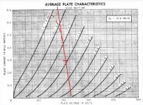
The issue is that the AC load is really hefty. If you look at Michael's load lines you see that the load line (AC) is steep. The plate load resistor of the driver is going to be swamped by the AC load. You only need to carefully choose it to get the tube to idle at a good point.
It seems that by the wording of your question that you maybe think that triodes automagically have less distortion. They usually do, but it turns out that they work well for steep load lines. That's not to say that you can't find a good spot for a triode to work well, but just look at the D3A load line in Michael's drawings. It looks good.
What is not shown in his graphs is the effect that cathode degeneration will have on these characteristcs. They will even out the spacing of curves and flatten them out. Triodes will look more like pentodes. Pentodes should flatten out even more and I imagine spacing would even out more.
Is it possible to draw characteristics in SPICE to show how the D3A and 12AX7 (or any pentode and triode) curves would change with cathode degeneration? I think that would be useful for some that are struggling with the idea.
My take on the issue is that the first stage of a schadoid amp is a V-I converter (ie current source) which feeds into an I-V converter (the output stage).
An ideal current source (driver) has infinite output impedance. The output impedance of a driver with unbypassed cathode resistor is Rp in parallel with Ri*(mu+1) (where Rp = plate resistor and Ri = internal resistance)
ie 1/Rp + 1/ Ri*(mu+1)
Because pentodes usually display greater internal resistance and gain than triodes, they are inherently easier to configure into a high output impedance driver. A pentode with ideal driver characteristics will always achieve a greater Zo than an ideal triode. However, a carefully implemented triode driver can still deliver good results (do a search on any forum for builder feedback on the RH84).
When reading some of the comments on this post, please be aware that a while ago there was a rather bitter debate between Mr Kitic (designer of the RH84) and some of the current contributors over the design of schadoid amplifiers. Some contributors' comments still appear to be refracted to some degree through the prism of this discord.
Last edited:
You see so many claims of RH84 being able to pump out anywhere from 4-10W.
I recall Zob claiming it should make 6W SE? I couldn't get his past the 1st Watt
without G1 beginning to forward conduct! After superdrive inspired A2 mod, his
RH84 worked just fine (on that one channel). I didn't do anything to increase
plate resistance of the driver triode. Though what I saw on scope suggested it
probably would have helped.
There is no Schade when both drive and feedback all leaks out G1 as a diode.
I still believe a Triode's plate does not present optimally stable impedance for
accurately driving Schade network. But there are plenty worse ways to screw
up a partial feedback than driving from a slightly curvy impedance. Zob's RH84
was proof enough of that for me.
Last edited:
OK. SpreadSpectrum, if I am understanding you correctly you are saying the the Schade feedback makes the input impedance to the output tube effectively very low and this low impedance (steep AC load line) causes the pentode driver to have a better distortion picture than it would with a more normal (higher) resistive load. Is that right? It also appears that the DC load line is much less critical than normal.
With all that in mind would it be reasonable to use say a pentode LTP phase splitter with plate to plate feedback for each output tube to its respective driver's plate and just set the bias and load resistors for reasonable DC conditions? It would also seem that the PI load resistors might not need to be as carefully balanced as usual either since the AC load will presumably be much lower than the plate resistors anyway.
If one wanted to use cathodyne I suppose that just inserting a CC driver between the PI an output tubes should work just as well.
Finally what do you think of tubecad's idea of using the path trough the feedback resistor to supply plate current for the driver rather than having the normal plate load resistor to supply current to the driver?
Last edited:
It depends. Look at the driver load line below, where as the gm of the output tube decreases toward it's low current extreme, the load line of the driver will curve over due to the decreasing effective load impedance of the feedback network. This will certainly change the distortion spectrum of a triode, but not so much with a pentode. What's happening is that at the low-gm end of the output tube swing, the driver tube, be it triode or pentode or MOSFET, is at it's high gm end of the swing. This results in 2f distortion cancellation. With a triode driver, some of the cancellation will be cancelled by the triode's own plate resistance. This is seen in the loadline as a difference in driver plate swing as the loadline curves over vs. what it would be with a straight line. The result could be some odd harmonic distortion. Pentode and MOSFET drivers (high impedance V-I converters) produce the same current swing regardless of the load curve, allowing the drive voltage to increase more at the output tube's low-gm end, resulting in (hopefully) better cancellation. Or at least less generation of odd harmonics.I have no opinion on the triode v.s. pentode driver question in large part due to lack of knowledge. I am hoping to reduce my ignorance here. When using Schade the feedback imposes linearity on the output tube giving it more triode like characteristics right? As I understand it the feedback acts only on the output tube and has no effect on the distortion spectrum of the driver itself. Is that correct?
Yes ;-) Both I thinkI understand that the overall level of distortion (and hopefully the distortion spectrum) is better using a pentode driver. Is this because the improvement in the distortion spectrum of the output tube is far greater than the smaller negative contribution of the pentode driver or is the distortion of the driver somehow improved or cancelled in this circuit?
You could optimize the driver load line to cancel the distortion of the output tube, or create the overall harmonic profile you want. The voltage swing is relatively small, only driving a pentode or beam tetrode grid. This combined with the low impedance of the feedback network, favor a pentode driver, although some triodes are OK in this respect. The main problem with the triode is that it's Rp is in parallel with the feedback and it kind of works against the feedback e.g. when the feedback current is weakest, the triode's Rp is lowest. If the Rp is high or linear, it may be less of a problem.I presume that it is still pretty important to optimize the plate load on the driver for minimal high order distortion given that the voltage swing is bound to be pretty large.
The big difference between those two approaches is going to be the plate resistance and OPT impedance, probably resulting in a different damping factor compromise. I would sure go for local feedback on the output stage and a pentode driver, maybe another 6BQ5 😎Any help in understanding the issues is appreciated as I am contemplating a PP 6BQ5 project and partial feedback is a possible option (as is simple UL without FB).
PS wow a lot of stuff happend while I was typing!
"With all that in mind would it be reasonable to use say a pentode LTP phase splitter with plate to plate feedback for each output tube to its respective driver's plate and just set the bias and load resistors for reasonable DC conditions? It would also seem that the PI load resistors might not need to be as carefully balanced as usual either since the AC load will presumably be much lower than the plate resistors anyway."
Sure, like the Millett DCPP "red board" amp or Gary Pimm's Tabor amp or...
"Finally what do you think of tubecad's idea of using the path trough the feedback resistor to supply plate current for the driver rather than having the normal plate load resistor to supply current to the driver?"
like the DCPP or the Tabor or...
It's a great idea!
As pointed out, degeneration using an unbypassed cathode resistor results in high, linear plate resistance and makes for a better V-I converter
Attachments
Last edited:
"Any help in understanding the issues is appreciated as I am contemplating a PP 6BQ5
project and partial feedback is a possible option (as is simple UL without FB)."
Rather than abusing plate to plate for partial feedback: I think I'd Schade my output
pentodes by standing cathodes on 0 and 16 output taps, and grounding 4 instead...
Then you can use triodes to drive without any issues.
Last edited:
It has been so long since I looked at those two amps that I had forgotten their basic topology.
OK, it is starting to take shape now. I am not fond of messing with CCSs so either a traditional LTP or cathodyne with driver seems to be my current trajectory (though boozehound's choke tailed pair is a tempting but expensive diversion). Interesting idea using EL84 as output and driver as it would solve the "no small signal pentodes in current production" issue. Will have to look at rp to see if there is any problem there. Otherwise just pick a really common small signal pentode and buy some spares right now.
Those strange compactrons with small signal and power pentode in one do kinda of play to my oddball contrarian side though. 😉
I have run across a couple of interesting designs that take some or all of the partial feedback to the cathode of the drivers rather than the output tube grid (driver plate). Wonder what the plusses and minuses of that are.
Kenpeter; not sure I understand what you are proposing.
ARCDB - ST-70-C3
Take a quick glance at the ST-70-C3 schematic,
particularly how output stage is cathode Schaded...
This also puts the OPT in the loop for correction.
Good or bad? I think good.
You see so many claims of RH84 being able to pump out anywhere from 4-10W.
I recall Zob claiming it should make 6W SE? I couldn't get his past the 1st Watt
without G1 beginning to forward conduct! After superdrive inspired A2 mod, his
RH84 worked just fine (on that one channel). I didn't do anything to increase
plate resistance of the driver triode. Though what I saw on scope suggested it
probably would have helped.
There is no Schade when both drive and feedback all leaks out G1 as a diode.
I still believe a Triode's plate does not present optimally stable impedance for
accurately driving Schade network. But there are plenty worse ways to screw
up a partial feedback than driving from a slightly curvy impedance. Zob's RH84
was proof enough of that for me.
An RH84 will put out around 4W. Claims of 10W out of a single EL84 are totally outlandish. I am at a loss to find a possible cause for your findings, which do not concur with mine or any of the builders with whom I have corresponded. They also appear to contradict virtually all the positive builder feedback posted on multiple forums. I believe Planet10 has compared his build to some VERY esoteric opposition with favourable results.
- Status
- Not open for further replies.
- Home
- Amplifiers
- Tubes / Valves
- Attempt at giving back: 6L6GC SE amplifier