Hello,
As part of a MIDI controller/mixer/interface I am trying to build, I want to use the PCM4104 4 channel DAC (PCM4104 | Audio DAC | Audio Converters | Description & parametrics). I am pretty sure I have the USB->I2S stuff figured out on the microcontroller I am using, and before designing the final board I want to hook up the evaluation kit to a PCM4104 and play with it for a bit. I know there is a $200 evaluation kit, but I figured I would like to make my own as a step towards the final hardware design.
I have very limited analog design experience, so I simply copied the data-sheet/evaluation kit reference design, and kind of half-assed the power supplies. I also used http://www.diyaudio.com/forums/digital-source/242668-new-dac-pcb-dual-pcm4104-8-channels.html as a reference for some stuff. My goal is to get the thing working for now, and later worry about performance optimizations.
I will be feeding this board +/-12v DC regulated by a pair of LM317/LM337 cheap modules I have around (suboptimal but I figured I'd wait with a better PSU for a later stage), and +9v DC from a lab PSU.
If anyone has the time, can you please take a look for any obvious mistakes/potential issues?
Note that this design will be completely open-source and I will be providing both the Eagle files as well as software once there is something to show. To my understanding there are not a lot of DIY 4 channel MIDI controllers/mixers around there. If anyone's curious the CPU will either be an STM32F4 variant or the new STM32F7.
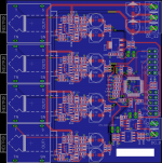
Schematics and PCB rendering are at Imgur: The most awesome images on the Internet
Thanks!
As part of a MIDI controller/mixer/interface I am trying to build, I want to use the PCM4104 4 channel DAC (PCM4104 | Audio DAC | Audio Converters | Description & parametrics). I am pretty sure I have the USB->I2S stuff figured out on the microcontroller I am using, and before designing the final board I want to hook up the evaluation kit to a PCM4104 and play with it for a bit. I know there is a $200 evaluation kit, but I figured I would like to make my own as a step towards the final hardware design.
I have very limited analog design experience, so I simply copied the data-sheet/evaluation kit reference design, and kind of half-assed the power supplies. I also used http://www.diyaudio.com/forums/digital-source/242668-new-dac-pcb-dual-pcm4104-8-channels.html as a reference for some stuff. My goal is to get the thing working for now, and later worry about performance optimizations.
I will be feeding this board +/-12v DC regulated by a pair of LM317/LM337 cheap modules I have around (suboptimal but I figured I'd wait with a better PSU for a later stage), and +9v DC from a lab PSU.
If anyone has the time, can you please take a look for any obvious mistakes/potential issues?
Note that this design will be completely open-source and I will be providing both the Eagle files as well as software once there is something to show. To my understanding there are not a lot of DIY 4 channel MIDI controllers/mixers around there. If anyone's curious the CPU will either be an STM32F4 variant or the new STM32F7.
Schematics and PCB rendering are at Imgur: The most awesome images on the Internet
Thanks!
Attachments
Last edited:
The first thing that jumped out at me is you're using NE5534 with no external comp capacitor so you may well run into oscillations. The 5534 uncompensated has a minimum noise gain of 3.
Hm, interesting. Any idea why it is omitted in the PCM4104 datasheet / evaluation module schematics?
Should I just put a footprint for one and experiment with a ~10-20pF cap?
Thanks for taking a look at this!
Should I just put a footprint for one and experiment with a ~10-20pF cap?
Thanks for taking a look at this!
I was going to give a direct answer to your first question but politeness has intervened 🙂
If you are interested in getting the best sound out of this I have at least one further suggestion about the opamp, that is change it to a JFET one (the 5534 is bipolar). With an opamp change you'll have no need for the extra capacitor as we can select one which will be stable.
If you are interested in getting the best sound out of this I have at least one further suggestion about the opamp, that is change it to a JFET one (the 5534 is bipolar). With an opamp change you'll have no need for the extra capacitor as we can select one which will be stable.
I don't have experience with OPA827 so it could be fine. My favourite (and I only have experience with the dual version) is ISL28110 which is available from Mouser.
The reason for going over to a JFET isn't for some nebulous reason that 'JFETs sound better' rather that it allows much lighter loading on the CMOS opamps inside the DAC chip. These seem to have PSRR which is quite dependent on output loading - the lighter it is the better rejection of supply noise. With a JFET the resistor values around the IC can increase considerably without a major noise penalty.
The reason for going over to a JFET isn't for some nebulous reason that 'JFETs sound better' rather that it allows much lighter loading on the CMOS opamps inside the DAC chip. These seem to have PSRR which is quite dependent on output loading - the lighter it is the better rejection of supply noise. With a JFET the resistor values around the IC can increase considerably without a major noise penalty.
Last edited:
Hm, a dual opamp would somewhat complicate the layout. I think I'll try the OPA827 and potentially the OPA227 (the dual version was used by someone else on this forum with this DAC) as they are all pin compatible.
I hope I can bother you with one more question - regarding increasing the resistor values, since filter design is completely foreign to me - how would I go about doing that? More than happy to do some reading if you can point me at the right direction / give me the right buzzwords to google 🙂
Thanks again!
The ISL28110 is a single, which is why I suggested it. I only mentioned the dual version because they're the same internally so a recommendation for the dual (which I have experience of) should also hold for the single.
Increasing the resistor values is just a matter of math - with a filter there are time constants formed by the multiplication of value of capacitance with values of resistance. Its important not to change those time constants significantly. So when we increase resistor values we decrease capacitor values by the same ratio. The reference book on filter design is by Arthur Williams - PM me and I can offer you some help towards obtaining that if interested.
Having studied your schematics in more detail and also looked at the DS for the DAC, I reckon you can simplify somewhat. For example the 100uF caps are really not required, they may have been added due to the otherwise lowish resistor values at the input. Likewise the 22pF right at the input serves no useful purpose.
Ah, misunderstood you about the opamp. I will give it a shot. Will PM to continue some of this discussion.
I'd suggest aiming for scaling the resistor values by a factor of 20X, the capacitors reduce by the same factor. The 560pF at the +ve input (C9) becomes 22pF due to the paralleled contribution of the opamp input capacitance, that on the other leg of the opamp (C10) turns into 27pF. C4 ->100pF.
R1,R2 -> 12k ; R3,4 -> 10k ; R5,6 -> 20k.
The remaining components don't get affected by this scaling factor.
R1,R2 -> 12k ; R3,4 -> 10k ; R5,6 -> 20k.
The remaining components don't get affected by this scaling factor.
Ha, simpler than I expected. Given that I have 4 channels to play with I think I will just set a different variation of this on each one, and finally see if I am one of those people that are able to hear the differences between opamps. I don't need to manually assemble any of this so might as well 😀
Excellent idea - you'll be listening for the differences in loading of the PCM4104's internal opamps. In which case the 20 factor could even be increased to 40....😀
- Status
- Not open for further replies.
- Home
- Source & Line
- Digital Source
- Attempt at evaluating PCM4104