
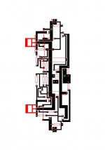
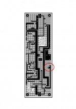
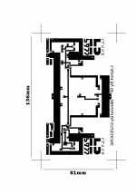
Final layout
I went over the layout again and checked the scale against the parts I have and this is pretty much it. I changed the trace for the drain on the outputs as I wanted them to be solid all the way along with no links.
I had to change the traces from R11 & 12 as the resisters I have are up-right.
I went over the layout again and checked the scale against the parts I have and this is pretty much it. I changed the trace for the drain on the outputs as I wanted them to be solid all the way along with no links.
I had to change the traces from R11 & 12 as the resisters I have are up-right.
Attachments
Looks very good. How is the paint going?
I'm thinking to continue with mine. By the way, I have tried, but it's difficult for me to find big elec. cap/50V of through-hole-to-PCB type around my reach. . . Haya. . . I might have to visit Korean Digi-Key web site and order Panasonic. . .
Cheers,
I'm thinking to continue with mine. By the way, I have tried, but it's difficult for me to find big elec. cap/50V of through-hole-to-PCB type around my reach. . . Haya. . . I might have to visit Korean Digi-Key web site and order Panasonic. . .
Cheers,
Paint
That takes soooooooo long to dry.
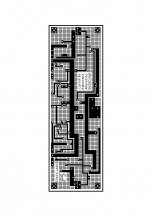
I am still working on that, have marked out the first of four power boards.
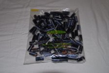
They are a big problem as I am using different caps. They are 2200uf 25v. So I will be using lots and lots of them. Which means I will need lots of board space.
I got 150 of these for $20 so I couldn't complain, but just look at the layout I'll have to use
That takes soooooooo long to dry.
I am still working on that, have marked out the first of four power boards.
They are a big problem as I am using different caps. They are 2200uf 25v. So I will be using lots and lots of them. Which means I will need lots of board space.
I got 150 of these for $20 so I couldn't complain, but just look at the layout I'll have to use
Attachments
Size
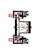
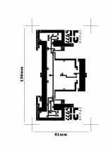
Check out the size of the board compared to your amp board😱
And I need to use four of them😀
But I just couldn't afford to buy 10,000uf caps. Hundreds of dollars.
I can't keep spending money, must watch my budget.
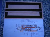
Pic is of the second board, the first one was a complete disaster..............I real mess ink went everywhere.
This second one I used tape to mark it all out then just filled in the spaces with ink. About 2-3 coats should be enough?
LAYOUT
What do you think about this, I am very worried about going ahead with this board as I have never maid or used anything like this before. And I can't afford to blow parts..
I just don't want to proceed unless it will work.
Check out the size of the board compared to your amp board😱
And I need to use four of them😀
But I just couldn't afford to buy 10,000uf caps. Hundreds of dollars.
I can't keep spending money, must watch my budget.
Pic is of the second board, the first one was a complete disaster..............I real mess ink went everywhere.
This second one I used tape to mark it all out then just filled in the spaces with ink. About 2-3 coats should be enough?
LAYOUT
What do you think about this, I am very worried about going ahead with this board as I have never maid or used anything like this before. And I can't afford to blow parts..
I just don't want to proceed unless it will work.
Attachments
25V caps on a 24V supply doesn't leave you much margin for safety (hopefully, you won't have unintended fireworks show) and you need to use how many of them? A power surge could leave you with a string of lady fingers going off (firecrackers) 
Try apexjr - look at the 12000uF computer grade caps for $1.99 each. Tell him you're from diyaudio and you might get a discount. No idea what shipping to NZ would be, but $20 for 10 will be plenty for a stereo F5 (imho).
(edit) Forgot the link:
http://www.apexjr.com/capacitorsR.html
Try apexjr - look at the 12000uF computer grade caps for $1.99 each. Tell him you're from diyaudio and you might get a discount. No idea what shipping to NZ would be, but $20 for 10 will be plenty for a stereo F5 (imho).
(edit) Forgot the link:
http://www.apexjr.com/capacitorsR.html
Probably right, but.....
Last page of F5 manual sites power supply using 120,000uf per side@25v
Means I'd need 240,000 = 20 x 12000@ $1.99 ea.
= $40 USD
=$80-90 NZD + Postage
So im still looking at another $100.
hmmmmmmmmmmmmm.........
no more money......🙁
Last page of F5 manual sites power supply using 120,000uf per side@25v
Means I'd need 240,000 = 20 x 12000@ $1.99 ea.
= $40 USD
=$80-90 NZD + Postage
So im still looking at another $100.
hmmmmmmmmmmmmm.........
no more money......🙁
Re: Probably right, but.....
I believe that the filter caps rated at 25V are useful.
I understand that the life of the filter caps is depending mostly on the rate of the operating vs. rated temperature of the caps.
Yeah. . . the manual accepts the "@25V". . .
Cheers,
enzedone said:
Last page of F5 manual sites power supply using 120,000uf per side@25v
...
I believe that the filter caps rated at 25V are useful.
I understand that the life of the filter caps is depending mostly on the rate of the operating vs. rated temperature of the caps.
Yeah. . . the manual accepts the "@25V". . .
Cheers,

enzedone said:couldn't complain
Notta badda at all.
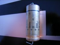
2200uf/25V Roederstein EG series were $2 for 1 or $1/pc if you bought 100, wholesale prices.
Pretty old, so you better juice 'm up slowly or Bida-Bada-Boom.
Layout
I've been playing around with the 'SP' layout and changing it to fit my parts.
What do you think?
I had to paste the components names over the top so some of the tracks are white in places..sorry
R18 is not the green line, but the resistor below this. The green line is a link.🙄
I've been playing around with the 'SP' layout and changing it to fit my parts.
What do you think?
I had to paste the components names over the top so some of the tracks are white in places..sorry
R18 is not the green line, but the resistor below this. The green line is a link.🙄
Attachments
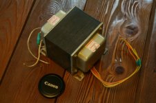
OK. . . here is my 2nd-hand EI trans of 2x25V that I'm going to use for new F5. I do not remember whether this is at 500VA or 600VA. Aee~ doesn't matter~ this will work anyhow. . . The physical size is W140mm x H95mm x D105mm and weighing 5.5Kg. The secondary ac will give me max dc 35V, of which about 12V would be dropped across PSU regulatior complex, and of which about 23V would be used for the rail voltage.
To fill in component collection box fully with items I could not find here, today I had to order some parts from Digi-Key:
- Panasonic 33,000uF/35V filtering caps, through-hole type. Why not ...uF/50V? Simply to save $.
- ZTX450/550
- 5ohm NTC Thermistors (CL-40A)
(10 pieces each)
Total price is higher than I expected, but still much cheaper than one pick-up which I had to replace for my Marantz CD player SA-14. I wonder why the pick-up is to be so expensive
Chears,
🙂
Attachments
Reference: Post #122
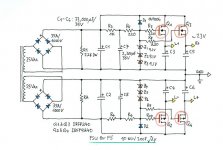
I change my mind. I want to make PSU a bit simpler for my F5.
Original: Bridge - C(33,000uF/35V) - R (4*0R47 3W) - C(33,000uF/35V) - ...
Now: Bridge -C(33,000uF/35V) - ...
And, I have new R5 and R6, expecting that the zeners might become better protected from the ripple voltage.
I'd like to go with this unless there is any comment.
Cheers,
🙂
Attachments
Not any comment from you. . . ?
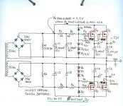
Okay, waiting your comments, I have pondered whether having of only one C1 (33,000uF) at the entrance to the active regulator is enough for the size as a filtering cap. Mmm. . . enough or not. . .? Assuming the dc load current of maximum about 10A, I have tried to approximate the ripple voltage at C1 on a simple calculation and found that the peak-tp-peak ripple voltage is about 2.5V. If this approximation has been in order, I expect that the 2.5V ripple is not big, and it could be easily filtered by the active regulator. If so, yeah. . . having of only one C1 is likely stamped "approved". . .
I have increased R5 (and R6) to 1K to have zener current of 4mA. The R5, however, seems to have a negative effect too. According to Papa, D1 is arranged for safety in case the C2 is to be dischraged quickly. The R5, however, interupts the current flow, by locating between D1 and C2. . . Hmm. . . mmm. . . I might feel better with additional safety means of the back-to-back zeners between G and S of the Mosfets. . . Why worry. . . ? You have plenty of zener diodes.
I think I go with this version dated 11NOV2008.
Cheers,
🙂
Attachments
Power supply
Why not use the standard one offered in the service manual?
Is it that you are after a regulated power supply? and why do think they are better?
I am going to use the standard one which will mean I could get away without a board.
Why not use the standard one offered in the service manual?
Is it that you are after a regulated power supply? and why do think they are better?
I am going to use the standard one which will mean I could get away without a board.
- Status
- Not open for further replies.
- Home
- Amplifiers
- Pass Labs
- ATC SCM7 . . . with Papa's diy amp?