Hi I bought two ATC means SM75-150 STD 8ohm for my PROAC E.B.S
and I want to replace them brings 16ohm source
I would know someone tell me that I have to change
thanks
and I want to replace them brings 16ohm source
I would know someone tell me that I have to change
thanks
An externally hosted image should be here but it was not working when we last tested it.
Last edited:
Guessing here. Add a resistor in series equal to value needed to make Re of new driver equal to Re of old driver?
not how it is done or the value to be put could tell me the crossover scheme to put the new ATC SM75-150 8ohm
I think that whole section for the mid range would need to be redesigned . All new values for L2 , L3 C3 C4 and R2 .
For the best sound, you would need to measure your new ATC 75-150S_8ohm in the actual cabinet and design a new crossover. You would probably want to use a similar filter type.
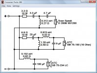
For a quick test, you could add a 5.7-ohm resistor in series with the new ATC 75-150S_8ohm so a "similar" 10.9-ohm impedance is seen by the crossover circuit. AND you would want to reduce the 6.8-ohm padding resistor at the front-end of the ATC 75-150S_16ohm crossover to about 1.1-ohm resistor (need to experiment with this value) to "approximate" the original SPL/watt as seen by the amplifier for SPL balance. DON"T EXPECT GREAT SOUND WITH THIS PATCH!
Attached example ATC factory crossover for the ATC 75-150S_8ohm suggest the need for R-L-C notch filters for "optimum" sound.
Attachments
Here's what I said in a PM to miguelnoda:
I said that knowing nothing about the two drivers or what the differences might be.
Traditionally, going from 16 ohms to 8 ohms on the mid or any other filter, you'd double the capacitor values and halve the coil values. But when I modelled it, it made little difference.
I think you can try your 8 ohm mid with the existing filter. Be careful that the 6.8R at the input holds the impedance up to safe levels. Don't go below 3.3R if you adjust mid level. I also found, strangely, that the tweeter works best positive polarity. Worth trying IMO.
I said that knowing nothing about the two drivers or what the differences might be.
atc sm75-150 standar
You could help me redesign
the one I have is the standard model no super or S
91dB.
thanks
You could help me redesign
the one I have is the standard model no super or S
91dB.
thanks
You ARE having a laugh, I assume! 😀You could help me redesign
the one I have is the standard model no super or S
91dB.
thanks
That would be a huge project involving finding factory frequency response and impedance graphs for both dome mids. FRD and ZMA files.
Just try what I said. Nothing will break. Not hard to adjust levels if something goes seriously awry. I bet it ends up OK.
Why did you change the units, by the way?
Last edited:
I thought that too. ATC supplies replacement diaphragms for their midrange domes don't they? Also, is it definitely an 8 Ohm unit? The standard unit is normally 16 Ohms unless you specify otherwise.
You can still experiment with adding a 5.7-ohm resistor in series with your new SM75-150_8ohm to get closer to the Re=10.9 of the SM75-150S_16ohm, AND ALSO experiment with significantly reducing the 6.8-ohm resistor at the front end of the Proac midrange crossover to test SPL levels.
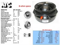
The SM75-150S has a sensitivity of 94db SPL
The SM75-150 has a sensitivity of 91db SPL
For smooth SPL/freq, you will need to either: 1) design a new 3-way crossover; 2) add series resistors to the input of the Proac tweeter and bass crossover circuits to lower their SPL closer to the new 91db midrange.
=======
If you are not satisfied with the sound of a "resistor-patch" to the Proac crossover, it will cost about about $200/speaker for LR4 3-way good-quality crossover parts.
You should measure the DC resistance of your voice coil to confirm it is ~5.3-ohms as spec'ed for the 8-ohm standard unit.
Do you have the simple setup to measure driver impedance vs. frequency?
Do you have tools to measure SPL vs. frequency?
Well, LineSource, TBH, I still haven't a clue what the difference is between an ATC 8 or 16 ohm is. 😕
The S designation seems to refer to a bigger magnet and more efficiency, maybe 94dB rather than 91dB.
Here's Jeff Bagby's take: http://studio-hifi.com/images/ATC75-150S_JeffBagby.pdf
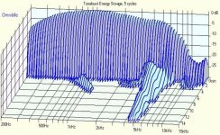
Evidently the best midrange in the World. Well, if you believe it. It's still a crummy soft dome with all the centre resonance which we have come to expect at 5kHz in the waterfall. 😀
The S designation seems to refer to a bigger magnet and more efficiency, maybe 94dB rather than 91dB.
Here's Jeff Bagby's take: http://studio-hifi.com/images/ATC75-150S_JeffBagby.pdf
Evidently the best midrange in the World. Well, if you believe it. It's still a crummy soft dome with all the centre resonance which we have come to expect at 5kHz in the waterfall. 😀
Attachments
Well, LineSource, TBH, I still haven't a clue what the difference is between an ATC 8 or 16 ohm is. 😕
The S designation seems to refer to a bigger magnet and more efficiency, maybe 94dB rather than 91dB.
Here's Jeff Bagby's take: http://studio-hifi.com/images/ATC75-150S_JeffBagby.pdf
Evidently the best midrange in the World. Well, if you believe it. It's still a crummy soft dome with all the centre resonance which we have come to expect at 5kHz in the waterfall. 😀
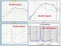
While it may not change the ATC's FR much going from 16 ohms to 8 ohms using the same filter, the Q at the Fc's will change, and the response lumps will change as a system. Due to the 8 ohm unit looking peakier at the extremes of its useful range in the image Linesource linked, you'll need a lower Q filter to achieve the same system response. Being that the change is going from 16 to 8 in terms of load, the xover will have a Q of half what it did before, and suppress the peaks with more damping using the 8 ohm unit, and it has the lumpier response inherently.
If anything, the lower Q with the lumpier 8 ohm driver should not change too much to the negative from the smoother 16 ohm and higher Q system. At any rate it may be dipped at Fc instead of flat, and definitely not peaked, but that is a worst-case guess.
Later,
Wolf
atc 75-150 std
replace and substitute 6.8 ohm resistance for one of 3.3ohm to see how it will
Cheers
replace and substitute 6.8 ohm resistance for one of 3.3ohm to see how it will
Cheers
Evidently the best midrange in the World. Well, if you believe it. It's still a crummy soft dome with all the centre resonance which we have come to expect at 5kHz in the waterfall.
To be fair, the resonance starts -20dB below main level and they do say operating range is up to 4kHz. If you don't have an issue with that 5kHz tail trailing off, the rest of the CSD (and the smoothness of the FR) is perhaps the cleanest of any mid around.
The only way to build a good sounding crossover is to take quality measurements of the actual speakers in their box.
===============
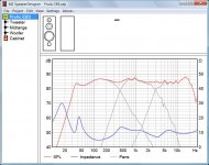
Pulling frequency and impedance data from the ATC website, and from diy speaker projects I took your crossover circuit and ran two simulations.
1) using ATC data, probably LARGE baffle board testing, and experimenting with front-end resistor power resistor and series resistor attached to 8-ohm ATC. Very good results.
2) using data from a diy project on the web which had a very small area baffle, and experimenting with capacitors, front-end resistor power resistor and series resistor attached to 8-ohm ATC. Changing crossover capacitor values was also required to get a decent curve match.
Hope this motivates you to download Xsim and SPL Copy free software and make a few measurements.
Xsim circuit-type crossover design tool
SPL copy S/W automatically traces frequency and impedance plots for FRD and ZMA data files
===============
Pulling frequency and impedance data from the ATC website, and from diy speaker projects I took your crossover circuit and ran two simulations.
1) using ATC data, probably LARGE baffle board testing, and experimenting with front-end resistor power resistor and series resistor attached to 8-ohm ATC. Very good results.
2) using data from a diy project on the web which had a very small area baffle, and experimenting with capacitors, front-end resistor power resistor and series resistor attached to 8-ohm ATC. Changing crossover capacitor values was also required to get a decent curve match.
Hope this motivates you to download Xsim and SPL Copy free software and make a few measurements.
Xsim circuit-type crossover design tool
SPL copy S/W automatically traces frequency and impedance plots for FRD and ZMA data files
Attachments
ATC 75-150 8ohm
hello I tried a while changing the resistance of a 3.3ohm and 6.8ohm not give me good results.
values in the circuit need to change to sound like that of 16ohm.
The filter circuit is that of EBS PROAC
SALUDOS
hello I tried a while changing the resistance of a 3.3ohm and 6.8ohm not give me good results.
values in the circuit need to change to sound like that of 16ohm.
The filter circuit is that of EBS PROAC
SALUDOS
I have done the schematic of atc 8 ohm
And it goes very well thank you very much
I only have a doubt that the watts of the resistors and the resistance of the coil
And it goes very well thank you very much
I only have a doubt that the watts of the resistors and the resistance of the coil
proac ebs
I could replace the 35UF capacitor with one of 47UF that you could simulate with your programs
saludos
I could replace the 35UF capacitor with one of 47UF that you could simulate with your programs
saludos
Last edited:
Hi Miguel,
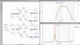
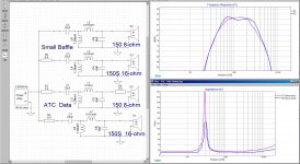
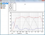
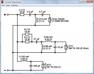
Now that Troels Gravesen has published his measurements of the standard ATC SM75-150 16 ohm (ATC-SM75-150) it's more possible to answer your question. I get the best match with the original response when all components of the midrange filter are approximately halved or doubled.
Attachment 1+2 is the original ProAc EBS using the 16 ohm midrange unit, attachment 3+4 is the modified version using the 8 ohm unit. Note that all drivers are positive polarity. My simulation does not at all confirm the inverted tweeter shown in the original schematic.
Attachments
- Home
- Loudspeakers
- Multi-Way
- ATC 75-150 STD