Hello,
I’m looking for assistance with reverse engineering the crossover network from a pair of speakers. Specifically, I would like to know if it’s possible to create an accurate schematic based on detailed photos of the crossover components and layout. There aren't schematics available online, sadly.
If feasible, I’m happy to provide high-resolution images of the crossover board, including close-ups of the components and their connections. The goal is to document or potentially replicate the design for analysis or restoration purposes.
Any guidance or support in interpreting the layout and developing a schematic would be greatly appreciated.
Best regards,
Michael
It might be possible.
An experienced designer will probably see what topology is used and can figure out the most likely configuration.
Lets give it a shot...
If its a current model of a commercial loudspeaker I would avoid helping you so please let us know what speaker it is.
An experienced designer will probably see what topology is used and can figure out the most likely configuration.
Lets give it a shot...
If its a current model of a commercial loudspeaker I would avoid helping you so please let us know what speaker it is.
Last edited:

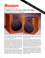
The crossover for those two-way speakers shouldn't be too difficult to work out. It will be interesting to see how many components it contains. The manufacturer's specifications from 1999 for the VR-M60 state that the crossover frequency is 2500 Hz, although another document states that it is 2700 Hz. These speakers also had provision for bi-amping.It’s an older Boston Acoustics speaker from 1999. The VR-M60.
Last edited:
Why do you want to do this?Hello,
I’m looking for assistance with reverse engineering the crossover network from a pair of speakers. Specifically, I would like to know if it’s possible to create an accurate schematic based on detailed photos of the crossover components and layout. There aren't schematics available online, sadly.
If feasible, I’m happy to provide high-resolution images of the crossover board, including close-ups of the components and their connections. The goal is to document or potentially replicate the design for analysis or restoration purposes.
Any guidance or support in interpreting the layout and developing a schematic would be greatly appreciated.
Best regards,
Michael
A schematic alone, will only tell you about 20%, (if that much ), of what's going on.
Last edited:
I’m trying to better understand how they accomplished the end result and I’m taking inspiration from this design to use for my new project.
If you have a mic, measure the individual driver responses, and attempt a x-over either in a sim or for real. Then look at how they did it, and see if they took any shortcuts that you might not. There's a hundred ways to do a speaker x-over. Odds are high that they went with one of the lower cost options, since profit is important for staying in business. Higher cost does not necessarily mean better, but sometimes a better x-over may sound pretty much the same as the cheap one to 8 people out of 10. The people that hear a difference might be willing to pay extra for it, but some may not.
All done here:
Can someone help me with drawing a schematic for my Boston Acoustics VR-M60? BA doesn't share schematics unfortunately, and I'd like to see this crossover in schematic form to get a better idea of what components do what.
I tried and got very discouraged based on the number of components and things in parallel, but then seem to be crossing over to the other side (it's a bi wired design)
I'm trying to gain a full understanding of the circuit and what component does what, etc.
I tried tracing the board, and still got confused trying. Anyone else good at this?
At the end, I want to have...
- ouimetnick
- Replies: 15
- Forum: Multi-Way
I’ve already looked into the forum and the crossover the guy presented is not the one found in that speaker. I own 4 pairs of the VR-M60 and verified. I don’t think that gentleman realized it’s not a factory crossover.
Measurements posted by a user on ASR: Details belowIs this your measurement? Was it on a stand, and away from walls, etc?
"I thought this group would be interested in how some vintage speakers compare to each other under the same measuring conditions. I have a collection of vintage speakers and simple measuring setup. No Klippel machine for me! I measured the frequency response of each speaker with:
- Laptop PC with Creative soundcard
- REW software
- Dayton UMM-6 microphone, with calibration loaded in REW
- Random Denon amplifier
- 1 meter distance, on the tweeter axis
- 20x24 garage with hard floor and 9.5' ceiling
- Small amount of damping on the floor
Here's the setup."
Attachments


- Home
- Loudspeakers
- Multi-Way
- Assistance with Reverse Engineering Crossover