Hi,
I just ordered this TK-2050 Amp.
To my surprise it came unassembled,without a list of parts.
I can guess where to put the bigger components, but no chance with the SMD parts. Does anyone have a glue where to get a list numbered list of parts. Or does anyone own the same amp and can take high-res photos, so I can identifiy the parts?
Thanks in advance.
Norman
Hm i cannot find anything on that link indicating this would be a diy kit, from what i can tell it should be preassambled.
Also a lack of assembly instructions suggests that if this is a kit, its intended for those that are already familiar with the tk2050 and know what parts go where.
Also a lack of assembly instructions suggests that if this is a kit, its intended for those that are already familiar with the tk2050 and know what parts go where.
Hm i cannot find anything on that link indicating this would be a diy kit, from what i can tell it should be preassambled.
That's why I bought it. But it came in parts, no further information included.
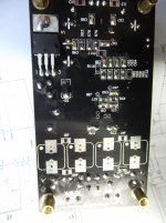
There you go. That board is OK.
You might consider inverting Ri and Rf resistors ( r57, r59, r71, r75) for a lower gain. Don't push it too much or you might toast the tp2050.
You might consider inverting Ri and Rf resistors ( r57, r59, r71, r75) for a lower gain. Don't push it too much or you might toast the tp2050.
Attachments
Last edited:
Thank you Virpz. That helps a lot.
But I still have problems identifying the parts. I tried looking up the imprinted codes in this database, but they don't match up the search results. Cann you recommend another database I might be luckier with?
Also some of the parts don't even have codes printed on. They're just light brown, same size as the others. Any glue how to find out which ones these are?
And at least can you tell me what BTL mode and stereo means, concerning the jumpers.
I hope my questions aren't to trivial and are to be found answered in FAQs I just haven't stumbled upon.
BTL usually means "bridge tied load" where a speaker is connected between two amplifier outputs and the signal to one amplifier is phase inverted.
Bridged and paralleled amplifiers - Wikipedia, the free encyclopedia
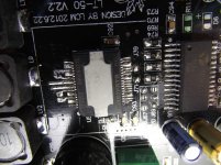
The light brown SMD parts (in the photo in your first link in post #1) are capacitors. SMD resistors usually have the value printed on such as 103 being 10K (10 and three noughts). Resistors are easily measured though if in doubt. Many DVM's measure caps.
Bridged and paralleled amplifiers - Wikipedia, the free encyclopedia
The light brown SMD parts (in the photo in your first link in post #1) are capacitors. SMD resistors usually have the value printed on such as 103 being 10K (10 and three noughts). Resistors are easily measured though if in doubt. Many DVM's measure caps.
Ok, I got what BTL means. But how do I have to handle these jumpers? Bridge them with solder?
Allright, my DVM can measure resisitors for sure. But it can't handle capacitors. Any other suggestion? Otherwise i would have to borrow one, but I doubt I know someone how ows a DVM that measures capacitors.
Allright, my DVM can measure resisitors for sure. But it can't handle capacitors. Any other suggestion? Otherwise i would have to borrow one, but I doubt I know someone how ows a DVM that measures capacitors.
Without the exact circuit and the board in front of me I wouldn't like to say regarding the jumpers. I'm guessing your just wanting normal two channel stereo so if there are any jumpers marked as such then they would be bridged with solder. Don't bridge any marked BTL.
There are ways of deducing the value of caps but all require test equipment such as signal generators and a scope etc.
There are ways of deducing the value of caps but all require test equipment such as signal generators and a scope etc.
Thank you Virpz. That helps a lot.
But I still have problems identifying the parts. I tried looking up the imprinted codes in this database, but they don't match up the search results. Cann you recommend another database I might be luckier with?
Also some of the parts don't even have codes printed on. They're just light brown, same size as the others. Any glue how to find out which ones these are?
And at least can you tell me what BTL mode and stereo means, concerning the jumpers.
I hope my questions aren't to trivial and are to be found answered in FAQs I just haven't stumbled upon.
Hi,
You should have three electrolytic caps, many 0.1uF caps, six 0.47UF caps ( the square ones, half a centimeter wide or something close to that) two 330pF and two 470pF caps with its values marked on the tape they came packed with.
As mooly already said; jumpers marked as BLT you should left open and jumpers marked as stereo you should join with solder.
You don't have the resistors that are needed for btl mode on this kit.
I purchased 12 boards like that and I tell you what happened. The guy who used to manufacture and assemble these boards is not doing it anymore, in the last few days he was selling them like that and the guy who sold it to you earned $ 10,00 bucks with ease. This seller should refund you. If I was you I would ask for a full refund and let others know that he is a "no, no".
Seriously, to get the tc2000 soldered is easy but soldering the tp2050 right in place is no joke. If you short it's pins there will be fire and then some smoke.
I will upload somo photos of the finished board and the schematic later when I can get my laptop.
[]'s
Like i've said you have many smd caps that are 0.1uF, two 330pF and two 470pF. All share the same look and so if the 330pF ( c84 and c83) and 470pF ( c81 and c82 ) have not been identified by label or anything like you will need to measure or buy new ones...
I have used 1mm solder to do the job and had alot of trouble with the tp2050 and so I recommend you 0.5mm wire.
Good luck
I have used 1mm solder to do the job and had alot of trouble with the tp2050 and so I recommend you 0.5mm wire.
Good luck
Attachments
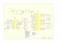
Not btl but paralelling?
Thank you Virpz for letting us know how to "BTL" this thing via the scematic (is it for the 2.2-version?) I bougt one of these boards cheap(est?) from goodluckbuy two months ago. It lasted some time and suddenly went up in smoke for no obvious reason. Apart from a little soldering and moddin...🙂 Maybe it has to do with the strange warning about "Europe" and voltage. But I used only 20 volts and 8 ohm. BTL it is alrady, but actually it is paralelling the two channels one have to do to get 100w and/or if one uses 4 ohm. It seems I must open all the shorted jumpers and vice verca?
I have bougt a already paralelled duoble 2050 board from Sure (on sale now 29$!!!)so I know the chip sounds much better than ANY AMP I'VE EVER HEARD!
I messed it up.
Soldering the caps and resistors worked much better than expected, but I wasn't carful enought with the TK2050 and bent some of the contacts whe using the desoldering braid. When I tried to straighten them one by one I ripped a contactplate on the board off.
It was a interresting experience soldering SMD parts, but for ICs I need some more practice.
So is there any shop, where i can get such a board assembled, tested and ready to use?
Cheers,
Norman
You need to prectice with SMD soldering. If the damage isn't to bad then it can be repaired with fine wire.
http://www.diyaudio.com/forums/parts/127924-working-smd-how-do-without-specialised-tools.html
http://www.diyaudio.com/forums/parts/127924-working-smd-how-do-without-specialised-tools.html
Thanks for the tut, but it's too late. I got mad and broke the board in half.
Anybody knows any other source for such boards or any other solution for 24V and over 50W per channel?
Anybody knows any other source for such boards or any other solution for 24V and over 50W per channel?
- Status
- Not open for further replies.
- Home
- Amplifiers
- Class D
- Assembling TK2050 Kit