I am more familiar with valve equipment but I bought myself an Armstrong 621 as a solid state challenge.
Unfortunately it has had quite a lot of work done on it previously including replacement of one of the trim pots and most of the transistors on that channel.
I was going to do enough to get it working via a lamp limiter and take it from there so I decided that the minimum would be to replace the output caps which were leaking badly, the smoothing cap and the trimpots. I unsoldered the existing pots and them realised that it looks as though both ends of the track are soldered to the same pcb track. It is difficult to tell for certain due to the previous work done on the amp. I suppose this would make the pot work as a 50 ohm rheostat with the maximum resistance at the centre of the track.
Is this right or am I missing something? The circuit diagram does suggest a rheostat rather than a potentiometer.
Thanks
Paul
That sounds a bit odd tbh, what would be normal would be for the middle wiper pin and one end pin to be soldered together or alternatively one end pin left floating.
Wired as you describe doesn't sound correct. Also 50 ohms (100 ohm preset) sounds quite a low value but as ever we would need to see the circuit details.
Its also important that when you replace the preset you initially set it to the end that gives minimum bias... and depending on the circuit that could be either max or min resistance.
So...
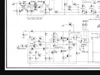
I can make out enough from an on-line image. 100 ohms is correct and the preset should be wired using one end pin and the wiper. The other end pin can be either connected to the wiper or left free.
Minimum resistance (so zero ohms) will give minimum bias current. Use a biggish preset because the wiper current is substantial... its a bit blurry but it looks like there is around 20 volts across the 2k2 feeding it which is around 10ma. Wiper current is sometimes quoted in data sheets.
Attachments
Thank you Mooley. I had assumed that one end was floating as that seemed logical and the circuit board has a "blob" next to one of the holes. The hole in question is very close to the pcb track that is connected to the other end of the pot track and because of the previous work done it is very difficult to see whether it should be connected or not.
There is a circuit diagram here The Armstrong 600 Series - Amplifier FAQ and diagrams
I am very tempted to leave the "blobbed" end disconnected. If I do so am I right in thinking that I should start with minimum resistance?
Thanks
Paul
There is a circuit diagram here The Armstrong 600 Series - Amplifier FAQ and diagrams
I am very tempted to leave the "blobbed" end disconnected. If I do so am I right in thinking that I should start with minimum resistance?
Thanks
Paul
Minimum resistance effectively shorts the diode to the transistor below and that condition gives minimum bias current because it gives the minimum possible voltage to be developed between the base's of the two drive transistors.
As you increase the resistance, this bias voltage between the base's rises and turns on the output stage increasing the bias current flowing.
The circuit shows the measuring point to be in the collector of the upper output transistor and that is fine, however it is easier to infer the current by measuring the tiny volt drop across one of the 0.47 ohm resistors.
You will need to know the recommended setting which is probably quite low, perhaps just 20 milliamps or so. That would give a voltage of just 9.5 millivolts across each of those 0.47 ohms. No signal applied for setting bias.
Thank you Mooley, that is what I thought regarding the trim pot connections. Someone previously has connected the ends together for some reason. The pcb track on one is a bit flaky so its difficult to tell for certain, but the other definitely has a piece of no original wire shorting them. I have no idea whether it worked like that as I did not like to switch it on in the condition in which I got it, even with a lamp limiter.
My next task was to measure what the actual resistance of those resistors is and possibly replace them
My next task was to measure what the actual resistance of those resistors is and possibly replace them
To low a bias will certainly work and even just 1 milliamp or so will effectively remove the worst of any audible distortion. With it wired as you describe it may well have been impossible to get the bias current to the recommended value.
If the bias is to high then the output stage will run to hot and could enter thermal runaway.
Designs these days have a more sophisticated method of generating the bias voltage (a Vbe multiplier) using a small transistor bolted to the heatsink to sense temperature.
If the bias is to high then the output stage will run to hot and could enter thermal runaway.
Designs these days have a more sophisticated method of generating the bias voltage (a Vbe multiplier) using a small transistor bolted to the heatsink to sense temperature.
Thank you Mooley. I have to get away from thinking about valves where a higher bias tends towards switching it off!
> I have to get away from thinking about valves where a higher bias tends towards switching it off!
Bias can be either way from "zero".
A transistor is OFF when Vbe is zero, ON when 0.6V or so.
A tube is ON when Vgk is zero, "OFF" when Vgk is quite -negative-, and can be REAL ON when Vgk is +positive+. (We seldom do that in audio, but positive grid is a thing.)
Yes, the OFF=Zero on transistors is convenient because we can short-out the bias string and have an amp that "works", just glitchy on small signals.
Just an update on the Armstrong. I looked at another example of the power amp board and one end of the tracks was floating. I bought a pair of Bourns pots and fitted them. The track of the original pot was open so maybe the ends were connected as a bodge to get it to work.
On checking the output transistors I found that those on the side that had a lot of work done on it were burnt out. Fortunately the rest of the transistors were ok and the rail and mid point voltages were reasonable. There was a .022uF cap between the base and emitter of one of the blown transistors for no apparent reason. Anyway I removed the cap and fitted some new 2N3773s to that side and I can now get the voltage drop across the .47 emitter resistors correct. I had to replace those as the originals had almost doubled in value.
One of the original electrolytics on the board was leaky so I will replace them all but it looks as though it is working now.
Thanks for the help.
Paul
The 0.47 had probably gone high as a result of the blown transistor and consequent overload. The 0.022uF if done by the manufacturer is typical of the kind of 'in production' modification made on a running basis as issues come to light.
There was only one .022 on one transistor, but it did look very similar to the .01 caps on the 82v rail. There has been a great deal of work of not exactly high standard done to the power amp board so it is difficult to say why it was fitted. I suspect that the original fault centred on those open bias "pots" - maybe something to be replaced on sight on these amps.
- Home
- Amplifiers
- Solid State
- Armstrong 621 bias trim pots