After reading the thread under
https://www.diyaudio.com/community/...rmer-snubber-using-quasimodo-test-jig.243100/
and further information concerning the steps for correct designing of a snubber network (for remove any ring-ring and RF stuff on the secondary side of transformer) under
https://github.com/analoghifi/Transformer-Snubber/blob/main/docs/related/Power Tips Calculate an R-C snubber in seven steps.pdf
and
https://github.com/analoghifi/Transformer-Snubber/blob/main/docs/related/Soft Recovery Diodes Lower Transformer Ringing by 10-20X.pdf
I wonder, why I don't find such snubber networks in commercial amplifier devices.
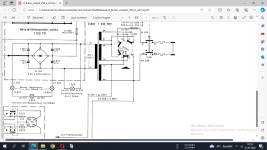
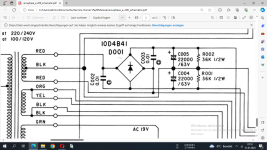
In most cases there are to find only a bridge rectifier (sometimes realized by single diodes) and big electrolytic capacitors for provide the necessary peak current.
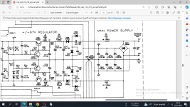
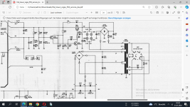
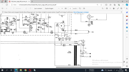
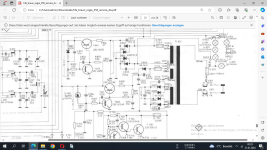
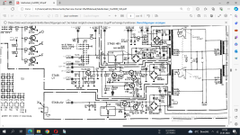
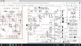
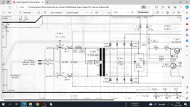
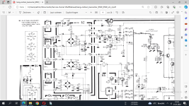
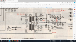
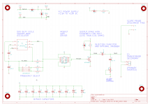
In the attachment you will find any circuit extracts of different snubber versions from various vintage amp models, but all without the necessary RC network (i. e. without a capacitor with resistor in serial connection).
Was this completely unknown at those days, that such snubber networks on power transformer as described in the above mentioned URLs are important for better SNR (as I know, the capacitors connected in parallel to the bridge rectifier diodes are always helpful to get a better SNR for AM - i.e. LW-MW-SW - reception without the typical rattling) ?
Is it possible that these snubber networks are often not necessary due to a special design of the power transformer ?
Thank you very much for comments.
https://www.diyaudio.com/community/...rmer-snubber-using-quasimodo-test-jig.243100/
and further information concerning the steps for correct designing of a snubber network (for remove any ring-ring and RF stuff on the secondary side of transformer) under
https://github.com/analoghifi/Transformer-Snubber/blob/main/docs/related/Power Tips Calculate an R-C snubber in seven steps.pdf
and
https://github.com/analoghifi/Transformer-Snubber/blob/main/docs/related/Soft Recovery Diodes Lower Transformer Ringing by 10-20X.pdf
I wonder, why I don't find such snubber networks in commercial amplifier devices.
In most cases there are to find only a bridge rectifier (sometimes realized by single diodes) and big electrolytic capacitors for provide the necessary peak current.
In the attachment you will find any circuit extracts of different snubber versions from various vintage amp models, but all without the necessary RC network (i. e. without a capacitor with resistor in serial connection).
Was this completely unknown at those days, that such snubber networks on power transformer as described in the above mentioned URLs are important for better SNR (as I know, the capacitors connected in parallel to the bridge rectifier diodes are always helpful to get a better SNR for AM - i.e. LW-MW-SW - reception without the typical rattling) ?
Is it possible that these snubber networks are often not necessary due to a special design of the power transformer ?
Thank you very much for comments.
Attachments
-
 NAD 216 snubber.png102.3 KB · Views: 78
 -
 Braun Regie 550 snubber.png400 KB · Views: 74
 -
 Braun Regie 450 snubber.png84.4 KB · Views: 71
 -
 Braun Regie 350 snubber.png282.7 KB · Views: 68
 -
 TFK TRX2000 Snubber.png160.6 KB · Views: 72
 -
 SABA 9240 Snubber.png370 KB · Views: 64
 -
 Braun Cockpit 250 snubber.png100.8 KB · Views: 66
 -
 Accuphase E206 snubber.png234.1 KB · Views: 66
 -
 Braun Regie 501 Snubber.png332.4 KB · Views: 63
 -
 B&O Beocenter 8500+9500 snubber.png147.4 KB · Views: 59
 -
 Grundig RTV500 snubber.png395.2 KB · Views: 65
 -
 Snubber Optimizer.png26.4 KB · Views: 64
 -
snubber network for power transformer.pdf1.3 MB · Views: 43
-
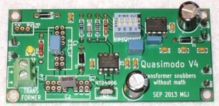 Quasimodo_V4_TH_photo.jpg173.2 KB · Views: 75
 -
snubber network design - Quasimodo_jig_revA.pdf817.4 KB · Views: 31
Last edited:
The Cambridge A3i in front of me has just capacitors across each rectifier diode.
The benefit from a snubber will vary with the characteristics of the diodes.
In big power diodes, specifying the turn-off characteristics is a big deal, too 'fast' a diode places a bigger load on the snubber.
Modern diodes may tend to be faster, as they may be optimised for switch mode supplies running at many kHz, not 50 or 60 Hz?
I would assume other aspects of the PSU are design also influence the requirements and benefits of snubber circuits.
RC snubbers are often effective in reducing both conducted and radiated emissions.
Sometimes it's a matter of the 'R' absobing energy which would otherwise go elsewhere.
Sometimes setting R to zero reduces the efficiency of the rectifier or switch too much.
Sometimes Earl Muntz wins and there is no 'R'.
Sometimes there's enough resistant implicit in the circuit.
It may be that the capacitor on its own limits the volts of the HF, but creates currents which radiate as interference.
The HF may be at frequencies which aren't usefully considered harmonics of the AC.
Sometimes snubbers are needed to prevent inductive volts damaging the switch/diode/thyristor.
In DIY audio kind of PSU's, it's maybe not always a big deal whether R is 5 or 0, as 5 is quite small?
We are talking about RC with microsecond time constants against 10 millisecond half cycles?