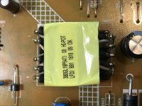
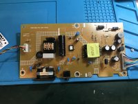
Snore... but why do you think it is suspect? Looks pretty clean to me. Perhaps you should look for smoke elsewhere.
The xfmrs and other magnetics in SMPS don't fail that often. I'd look elsewhere first unless there's heat damage on a magnetic part. You'd still have to look elsewhere.
The back light starts blinking after a couple minutes (voltage is dropping) when i was voltage testing the area probing one of the legs made the blinking stop / start ..
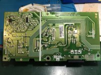
Check for dry/cracked joints on the underside of the PCB. You might need a magnifying glass but if so you will probably see a circular break in the solder around the lead. Reflow the joints with a soldering iron adding, ordinary 60/40, solder to make them shiny.
Last edited:
Hmmm. As I implied and others have suggested magnetic components are not generally prone to failure and if they do fail there is usually a tell tale in the form of soot or similar. An intermittent fault that goes away when probing would point to a poor solder joint cured by board flexure... Try looking further away from the transformer. A picture of the control IC and power device if used would be useful to get some idea of the type of control/convertor being used.
As others have suggested, when transformers fail they tend to leave skid marks. Look for over/under current regulation and feedback supplies. Get a schematic for it first.
If it is and external supply, probably cheaper to replace it and this is maybe just an exercise in fault finding.
If it is and external supply, probably cheaper to replace it and this is maybe just an exercise in fault finding.
Grumble. It does not really want to scream which part might be ill. It's a single switch flyback with the power switch integrated into the control IC, TNYXX? Is that thermal paste on the top of the IC or has the part number been obliterated. Can you scrape it off an give a number? The transformer pins associated with D903 are power back. It appears to have some sort of valley sensing on that winding. Drain of the internal switch is isolated with the slot. Main supply via FB902. The bucket of resistors and D902 are for transformer reset and snubbing of ringing. Secondary side diode into smoothing with no inductor says flyback. C915 and resistors are to snub ringing again. That's really just words. Do you have a scope?
Grumble. It does not really want to scream which part might be ill. It's a single switch flyback with the power switch integrated into the control IC, TNYXX? Is that thermal paste on the top of the IC or has the part number been obliterated. Can you scrape it off an give a number? The transformer pins associated with D903 are power back. It appears to have some sort of valley sensing on that winding. Drain of the internal switch is isolated with the slot. Main supply via FB902. The bucket of resistors and D902 are for transformer reset and snubbing of ringing. Secondary side diode into smoothing with no inductor says flyback. C915 and resistors are to snub ringing again. That's really just words. Do you have a scope?
The ic is one of these ,(LNK6776V Power Integrations | Mouser United Kingdom)
its not thermal paste , seems to be part of the chip , i do have a scope , only recently got my first one , i have not connected it to anything yet as i do not have an isolation transformer , and need to learn more first ..
Thanks for the link. Powerpad. Wise move on the isolation transformer but you might consider an isolated scope probe, could be just as expensive. If you feel confident you could try making some measurements on the secondary side just to see what sort of waveforms are present and how long the do or don't last. It's quite a simple convertor which is just generating a single bulk supply that is post processed by some of the other circuitry. You suggested that it does start up and run for a bit but the backlight was intermittent. It is possible that the fault lies elsewhere.
I've not heard of isolated scope probe i will have to have a look at them , i have replaced all the caps and re soldered all the pin joints , its an innolux panel and i have just replaced an innolux panel in another monitor with a flicker fault (backlight was good) so i am using that led strip to test , so same fault with a known good led strip .
The backlight now stays on for a good minute or 2 with voltage of around 34 vDC then they dim or flick low , Volts go down to 30 ish when its dim , sometimes a rapid flicker then it will go off completely ,0 volts , then unplug it for 5 mins or so and it repeats ..
willing to have a go at the secondary measurements with scope .
Simplest one with a meter would be to measure the bar end of D904, VOUT, with respect to the two commoned pins on the secondary of T901closest to C917, GND. It should be a stable so many volts. Same thing on your scope. See if it remains stable even when the backlight gives up. If so the problem is likely elsewhere. Not sure but if the backlight connector is CN804 then the controller is likely to be U801 possibly with Q801 and the core inductor close to it on the top being some sort of boost convertor via D802.
The volts on D904 is stable at 18.24 vdc when led is lit normally and rises to 18.6 when led is dim or off , backlight connector is CN804 ,
Q801 is one of these :
View attachment BA5-N10.pdf
At the gate of Q801 i get 2.8 vdc when backlight working drops to 0.4 v when backlight dim 0 when off.
Q801 is one of these :
View attachment BA5-N10.pdf
At the gate of Q801 i get 2.8 vdc when backlight working drops to 0.4 v when backlight dim 0 when off.
I assume you have made the measurements when there is no fault and done so with your multimeter set to DC rather than with your oscilloscope. The primary side Power Integrations controller does not directly regulate the secondary side voltage but monitors its power back winding on the primary side. As such you would not expect tight regulation of the secondary side bulk supply... hence the rise off load. Q801 will likely receive a PWM signal from U801 so again with a DC meter the numbers make sense. BVdss of 100V and 34V is consistent with it being a boost converter to supply an LED string. Not sure what the 4 isense wires do other than being four current sense points. Is it only the backlight that plays up and any hints as to what U801 is?
Yes all measurements done with multimeter in dc , other than backlight it works fine.
U801 is a 0Z9998MGN , voltage regulator ? , cant seem to find much info on it ...
U801 is a 0Z9998MGN , voltage regulator ? , cant seem to find much info on it ...
https://pdf1.alldatasheet.com/datas...C2/OZ9998/+01__WA-XDyD-cSdE.GG+/datasheet.pdf
Page 18) 19) External mosfet drive with what appears to be peak current mode control and over voltage protection/regulation. Could be bang bang control. Dimming via separate PWM input, presumably internal ground referenced switches on the LED strings in the isense terminals. Doesn't give any real design information. Really need to see what happens when it goes wrong with a scope.
Page 18) 19) External mosfet drive with what appears to be peak current mode control and over voltage protection/regulation. Could be bang bang control. Dimming via separate PWM input, presumably internal ground referenced switches on the LED strings in the isense terminals. Doesn't give any real design information. Really need to see what happens when it goes wrong with a scope.
- Home
- Amplifiers
- Power Supplies
- are small transformers like this available


