Thats something I observed in practice - there is no limit to the size of the filter cap just so long as you put a healthy choke between it and the rectifier valve. Still, as has been pointed out, there is no advantage to this approach over using silicon in the rectifier roll since the final cap is what you are listening to.
If you want the "sound" of an old fashioned power supply then you are obliged to make your final cap less than 50uf. Kiss good buy to any bass response if you do.
Shoog
If you want the "sound" of an old fashioned power supply then you are obliged to make your final cap less than 50uf. Kiss good buy to any bass response if you do.
Shoog
Last edited:
I sincerely apologize to both the moderation team and the others in this thread for my contribution to the general OT tackiness. Chalk up my weak moment to a lack of coffee, I suppose. It's a lame excuse to be sure, but it's the only one I have at the moment...
Now that that's over with, AJT's comment regarding "manna from heaven" is true even for us here in the States. A trip to the nearest Habitat ReStore, Goodwill, etc. can yield some pretty interesting finds. I once netted a Grommes "Little Jewel" PP 6V6 from a small thrift shop in NC. And a visit to the nearest hamfest of any size will still likely turn up a fair number of old WWII-era JAN tubes, command sets and the like some seventy years afterward - mute testament to just how massive that conflict really was.
And to delve even further into the topic of this thread...
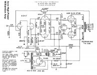
When building a tube circuit designed by others, I'll almost always use the rectification scheme called for in the schematic, regardless of the type. That way I can get a better understanding of the design's capabilities and weaknesses. One particularly memorable build involved the schematic shown below. The breadboarded circuit measured OK on the 'scope and sounded reasonably good, though the bass was somewhat flabby. It tightened up noticeably once I replaced the 5V4 with a pair of diodes, increased the filter capacitance and adjusted the B+ back down to a sane level.
Now that that's over with, AJT's comment regarding "manna from heaven" is true even for us here in the States. A trip to the nearest Habitat ReStore, Goodwill, etc. can yield some pretty interesting finds. I once netted a Grommes "Little Jewel" PP 6V6 from a small thrift shop in NC. And a visit to the nearest hamfest of any size will still likely turn up a fair number of old WWII-era JAN tubes, command sets and the like some seventy years afterward - mute testament to just how massive that conflict really was.
And to delve even further into the topic of this thread...
When building a tube circuit designed by others, I'll almost always use the rectification scheme called for in the schematic, regardless of the type. That way I can get a better understanding of the design's capabilities and weaknesses. One particularly memorable build involved the schematic shown below. The breadboarded circuit measured OK on the 'scope and sounded reasonably good, though the bass was somewhat flabby. It tightened up noticeably once I replaced the 5V4 with a pair of diodes, increased the filter capacitance and adjusted the B+ back down to a sane level.
Attachments
You're having better luck than I am at the thift stores. 🙂A trip to the nearest Habitat ReStore, Goodwill, etc. can yield some pretty interesting finds. I once netted a Grommes "Little Jewel" PP 6V6 from a small thrift shop in NC.
I do find useful electronic bits and pieces there, in particular, switch-mode power supplies, which IMO are perfect for valve heater power. (With the caveat that they don't come in a 6.3 volt rating, so you have to drop some excess voltage somehow.)
I've also found some interesting speakers - home Hi-Fi, sound reinforcement / P.A. speakers, and tons of boom-box speakers from the era of oversized boom-boxes.
But I've never yet found anything with glowing glass bottles in it!
-Gnobuddy
My choices are situation/application dependant:
Low-powered guitar and bass amps: Tube
High-powered guitar and bass amps: SS
Hi-Fi equipment (pre-power-tuner): SS
Low-powered guitar and bass amps: Tube
High-powered guitar and bass amps: SS
Hi-Fi equipment (pre-power-tuner): SS
There is no good reason to use tube rectifiers from an electronics point of view. The small difference in sound they produce due to sag is not worth the downsides.
Just my two cents worth.
Well..on second thought they do provide me with a way to make money repairing them...lol
Cheers,
Billy
Just my two cents worth.
Well..on second thought they do provide me with a way to make money repairing them...lol
Cheers,
Billy
Today i found out the hard way, when ck1006 ate its filament and stopped working after two days...
i had to put hv diodes there, and always more or less had buzz issues(with rectifiers). Randomly.
After ss diodes, dead quiet.....
so i think capacitance of filament windings does transfer peaks somehow
Sounds better too
i had to put hv diodes there, and always more or less had buzz issues(with rectifiers). Randomly.
After ss diodes, dead quiet.....
so i think capacitance of filament windings does transfer peaks somehow
Sounds better too
Thats something I observed in practice - there is no limit to the size of the filter cap just so long as you put a healthy choke between it and the rectifier valve. Still, as has been pointed out, there is no advantage to this approach over using silicon in the rectifier roll since the final cap is what you are listening to.
If you want the "sound" of an old fashioned power supply then you are obliged to make your final cap less than 50uf. Kiss good buy to any bass response if you do.
Shoog
Well, i guess that this classic Williamson based on Acro output transformers, amplifier shown by Mr Zenith has no bass response since the final cap is just 20uf? What a minute that would also include Dynaco MK3 amps as well. Those Dynacos were sure very popular for their poor bass.
I am actually glad that many people think valve rectifiers are obsolete. At least their price will remain low. Thanks!😀

Thats something I observed in practice - there is no limit to the size of the filter cap just so long as you put a healthy choke between it and the rectifier valve. Still, as has been pointed out, there is no advantage to this approach over using silicon in the rectifier roll since the final cap is what you are listening to.
If you want the "sound" of an old fashioned power supply then you are obliged to make your final cap less than 50uf. Kiss good buy to any bass response if you do.
Shoog
Shoog, if you have a moment, could you please reference this old fashioned psu which has "crappy" bass? I am curious.
Today i found out the hard way, when ck1006 ate its filament and stopped working after two days...
i had to put hv diodes there, and always more or less had buzz issues(with rectifiers). Randomly.
After ss diodes, dead quiet.....
so i think capacitance of filament windings does transfer peaks somehow
Sounds better too
I never used the ck1006 full wave rectifier - too expensive for me..
My experience with silicon vs. teevee damper diodes has been exactly the opposite. Of course we at talking 1N4007 vs. 6au4...
Bypass the 1N4007 with some small film caps helps with the nasty buzz (if you get it like I always seem to) or better yet, swap it out for CREE CSD-01060A.
I really like the CSD-01060A in pre-amp. Its a great device, and not too pricy as compared to its higher current and higher voltage cousins.
Wire properly, and no nasty buzz. Remember that wires have resistance and inductance, and about capacitance between them.
Comparisons between rectifiers are often made without indicating the conditions such as whether other noise sources and ringing were redundantly dealt with, damping was made equivalent with the change and grounding was correct.
A simple power supply doesn't have to be so sensitive, unless it is too simple.
A simple power supply doesn't have to be so sensitive, unless it is too simple.
I'm working on a little 2-watt practice amp prototype these days. The power supply starts with a 48-volt Hammond power transformer.
That transformer feeds a voltage doubler to create a roughly +150 volt rail, a voltage tripler to create a roughly +225 volt rail, and a voltage quadrupler to create a roughly +300 volt rail.
And then I realised that a negative rail would be useful for some experiments, so I used the 24v center tap of the same transformer feeding another voltage doubler to generate a -75 volt rail as well.
The diodes and filter caps are packed into a few square inches of protoboard. The board carries quite a few 1N4007 silicon diodes. And, you know what? There's no obnoxious buzzing.
-Gnobuddy
Comparisons between rectifiers are often made without indicating the conditions such as whether other noise sources and ringing were redundantly dealt with, damping was made equivalent with the change and grounding was correct.
A simple power supply doesn't have to be so sensitive, unless it is too simple.
Yes, grounding is most frequent cause of "sounding" of rectifiers!
For a novice like me, that has a hard time making PSUD2 match my own reality, it is convenient that I can adjust B+ by just subbing out various 5V rectifier valves.
For a novice like me, that has a hard time making PSUD2 match my own reality, it is convenient that I can adjust B+ by just subbing out various 5V rectifier valves.
I find i have very little difficulty getting psud2 to reflect reality.
Often the key is to enter the properties of the transformer correctly. there's a section about it in the help files, i think.
'course, overwhelming the impedance of the secondary by adding the plate resistors that used to be normal for tube rectifiers helps too.
An expensive and complicated way to adjust +/-10V 🙄For a novice like me, that has a hard time making PSUD2 match my own reality, it is convenient that I can adjust B+ by just subbing out various 5V rectifier valves.
Wire properly, and no nasty buzz. Remember that wires have resistance and inductance, and about capacitance between them.
ah, maybe I should be more specific. I don't always mean nasty buzz you can hear, but nasty buzz you can scope.
If you are unlucky, that nasty buzz you can scope can be physically felt on the power transformer as well as scope, although you don't actually hear it.
In any case, bypassing the 1N4007 with little film caps is really a must-do. Better yet, use the wolfspeed/cree device I noted instead (and bypass them too). they are a bit less than $1 apiece at mouser.
Ian
Yes, grounding is most frequent cause of "sounding" of rectifiers!
My grounding schemes are sound, and I always find the cheapest of the silicon rectifiers the noisiest.
In the same circuit, it is entirely possible to discover noisy damper diodes too, I have about a dozen genuine USA made RCA damper diodes that are in my opinion not usable. Luckily they cost me nothing.
I have a stock of coin-based GE damper diodes that perform wonderfully. they were less than $1 apiece, but to be frank and honest, they are more expensive since:
1. Still need to mount them in sockets (x2)
2. Still need to heat them
They do glow nicely, and they do bring up B+ slowly. And they can easily handle over 600V...
One piece of obvious advice I will share - lets say you might want more than 600V and are considering CSD-01060A. Just use two in series. This is much cheaper than the higher rated devices from Cree.
How come there is nobody proposing some nice slow-rise circuits for silicon? I think that's the real issue with silicon.
Ian
An expensive and complicated way to adjust +/-10V 🙄
The difference in B+ between 6AU4 to 6DA4 to 6AX4 is about -5V volts per step when you are drawing around 150mA. So changing your 6AU4 for 6AX4 usually drops around 10V. Different manufactures can also result in small changes.
It's exceptionally easy to swap them out. Same pins.. No soldering required... Still dirt cheap too.. and the nice slow start-up..
But I am most interested in anyone's cheap, reliable and easy to implement slow-start circuit for silicon rectification. 🙂
Last edited:
- Status
- Not open for further replies.
- Home
- Amplifiers
- Tubes / Valves
- Are rectifier tubes still relevant? Why would you use one, or avoid using one?