I am in the final stages of designing a programmable tube tracer. To reduce cost and complexity, I'm thinking about leaving out the ability to generate traces with positive grid voltages.
Are the plate curves at positive grid voltages generally useful, or can they be safely ignored?
Are the plate curves at positive grid voltages generally useful, or can they be safely ignored?
Are the plate curves at positive grid voltages generally useful, or can they be safely ignored?
If one wishes to use a zero or near zero bias triode with low plate voltage, then positive grid voltage is needed to get good current draw. Typical tubes would be transmitting types like 811, 805, 838 and 203A to name a few as well as other high voltage types. Since I'm old school, doing that is using the wrong tube. (or the tube wrongly 😉) But a lot of builders do it anyway because they have the tubes and insist on using them. I think the Japanese started this trend in the late seventies, early eighties in that MJ Stereo Technique magazine. (mu-sen-to-zee-ken) Now it's up to you if you want to cater to that use.
I think that it's useful for output tubes, not just zero-bias triodes, but also tubes which are happy being driven into AB2 (e.g., 2A3, 6L6/7027/5881).
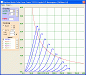
6P1P-EV data sheets show positive grid drive. I've been wondering if this implies the tube is designed for it?
6AQ5 shows positive grid voltage traces for grid voltage of +5, +10, +15 V. That would seem to me to imply that the tube IS designed for class B operation. and if the 6P1P is designed as a Russian replacement for the 6AQ5 then it too should be capable of class B operation.
So I think in there is good argument that positive grid drive testing might be useful even though the use in class B for audio is limited (but does exist, as I've seen it discussed).
It seems that positive grid voltages could be a useful feature.
I've been looking at less complicated ways of generating the positive and negative voltages. I have a 100V programable floating supply, so I can ground either rail, the question is the cheaptest and most effective way of doing that.
I originally was going to use a MOSFET bridge to switch the output and ground connections, but that seemed to complex, especially since you would need to use isolated gate drivers to turn on the MOSFETS. More recently I have been looking at just using a couple of SPDT dip relays.
The tracer uses a 12-bit ADC to measure the grid voltage. Because of the dual polarities, and the 0-5V input range of the ADC, my though was to use a TLE2426 "rail-splitter" chip to get a low impence 2.5V source and then use a 40:1 resistor divider to generate 5V to 0V as the voltage goes from 100V to -100V.
The other complication which I need to think about is protecting the supply from flash over from the plate in a gassy tube. The plate supply is fused, so it's easy to protect a negative grid. Just put a diode that conducts a positive grid voltage to ground. It is less clear to me how to protect the grid supply when it is positive. I guess I could always just use higher voltage components in the grid circuit. That means more expensive and larger 500V components instead of 100V components. I guess I still have some cost/benefit tradeoffs to consider.
Yves,
I agree that keeping the voltage stable near zero volts will be challenging. I think that it will probably be harder at slightly positive voltages than slightly negative ones.
Chris
I agree that keeping the voltage stable near zero volts will be challenging. I think that it will probably be harder at slightly positive voltages than slightly negative ones.
Chris
Have you thought of using a TL783 regulator for the grid bias supplies?
Linear Regulators - Standard Voltage Regulators - TL783 - TI.com
Linear Regulators - Standard Voltage Regulators - TL783 - TI.com
I am in the final stages of designing a programmable tube tracer. I'm thinking about leaving out the ability to generate traces with positive grid voltages.
Is your tube tracer for fun, or for profit? If you're designing a product you hope to sell to the public, will you limit your target audience if you eliminate this capability? If you are building it strictly for your own use, ask yourself if you ever design circuits that operate in that region.
Thanks for the link. I wasn't familiar with that chip. It definitely has a large input range. I'm actually working on a custom low noise switching supply to keep things as small and efficient as possible.Have you thought of using a TL783 regulator for the grid bias supplies?
Is your tube tracer for fun, or for profit? If you're designing a product you hope to sell to the public, will you limit your target audience if you eliminate this capability?
Right now we're in the hole for a couple of months of design time, but we do intend to sell it for a profit. Since positive grid voltages appear to be a feature that has some merit, I'm going to try to implement it. I'm not sure it increases the market all that much, but as long as it doesn't add too much to the cost, it's seems worth attempting. Worst case, I can leave it off if I can't get it working well enough.
Hi ChrisRight now we're in the hole for a couple of months of design time, but we do intend to sell it for a profit. Since positive grid voltages appear to be a feature that has some merit, I'm going to try to implement it. I'm not sure it increases the market all that much, but as long as it doesn't add too much to the cost, it's seems worth attempting. Worst case, I can leave it off if I can't get it working well enough.
I am a fan of making positive bias tube amp, but I will not buy a tracer because those tube are not left in the market too many and we can find out the data from hand book or from internet, they belong industrail and military stuff guality just same as the hand book show, NOS stuff should not have any problem, pull out stuff, we only use our ear to judge that is my one of the diyer's opinion
regard tony ma
Tony,
Thanks for the info about the availability of positive bias tubes. That gives me a good feel for how many customers might find the feature useful.
As far as using the curves from the data sheets, the point of using the tracer is that the curves in a handbook are only good plus or minus about 20 percent or so, so getting a trace from an actual tube can be useful, especially if you are trying to match tubes. The trace from a particular tube, especially an old one, can be far out of spec. It can be useful to verify that a particular tube is close to spec.
Before tracing a tube, the tracer will do things like check for shorts between elements, check the filament current, and run a gas test, so it can be used for both testing and tracing.
Chris
Is it a tester or analyzer?
Here's a thread that can give you some insight into the kinds of things a curve tracer is useful for beyond use as a glorified tube tester. There is not only positive grid voltage, but g2 drive (pentode g2 curves), g3 setting + and -, and some other imaginative ways to capture curves.
http://www.diyaudio.com/forums/tubes-valves/160240-suppresor-grid-used-feedback-7.html#post2085641
Features or hooks to get tabular data for the curves would be useful for analysis also.
Bipolar drive should not be that hard. If you use signed numbers zero is just another place on the scale. I.e. for the grid drive I would use a +/- power supply, a totem pole MOSFET driver, and voltage feedback such that the control voltage could be scaled to whatever you want for an output range of let's say -200 to +100 volts. I would do all of the voltages this way if I were building a sophisticated instrument.
Of course if it's only for use as a tester, then you could simplify things a lot.
You can just use properly scaled, phased, and offset waveform generators at 60 Hz for the voltages and capture with a sound card.
It would take me 2 months just to figure out what to build ;-)
Cheers,
Michael
It's meant to be more of an analyzer than a tester. The testing functions are performed before running the tracing functions to minimize the chance of damage to the hardware from a bad tube.
All of the supplies (plate, screen, grid, filament) are based on low noise switching supplies. The voltage range of each supply is limited by the design of the flyback transformer used to generate the output voltage. So, the plate/screen supplies are limitted to about 50 to 500V at 200ma max, the grid supply is limitted to +/- 100V at about 100ma, and the filament is limitted to about 2.5 to 30V at about 20W.
I certainly appreciate your comments about functionality that you would like to see. The intent is to be a very customer driven design. Since only the low level control functions are implemented on board, much of the functionality can be changed by just changing the software on the PC that it's connected to. The PC software will allow things like access to the trace data, as you suggested.
Another comment in a previouis thread also has me thinking about making a user accessible API so that the hardware can be controlled by user applications. The only problem there is making it bullet proof enough that the hardware can't be damaged by incorrect user code.
I took a look at the thread you recommended. Lots of good info. The design currently doesn't have a separate supply for G3, but the connections between the programmable suppplies and the tube sockets are via high voltage shrouded banana plugs. So, you could probably patch in an external supply and connect it to G3 and generate some traces to see the effect. Normally the G3 would be patched to ground (since the cathode is grounded) assuming that it is not internally connected in the tube.
Last edited:
The initial target is $699. With sufficient volume, we hope to get it down to $599. We're considering a promotion for the first 100 units or so, perhaps selling them for the ultimate target price of $599.So, what's your target retail price for a tracer?
At some point we will be looking for a few beta testers, so if you qualify, you could get one for free.
- Status
- Not open for further replies.
- Home
- Amplifiers
- Tubes / Valves
- Are Positive Grid Voltage Traces Necessary?