You are generalizing a lot here.
I generalize somewhat, not a great deal. Of course its possible to have a groundplane, I wasn't talking about what was possible, rather what exists. I do not recall seeing a board where one side was totally a groundplane but I admir it could exist. I've done a few layouts and etches - when I was a school lad (1970s) - and no I didn't care for the quantity of etchant I used (Ferric Chloride it was in those days). Rather I cared more for the time it took me to draw the board out with the etch resist pen (Decon Dalo 33 PC if I recall correctly), which was relatively expensive compared to the FeCl3.
Well, Abraxalito.
I also was a school lad back then.
But we used photoresist already then, but we also used that Dale-pen, but only for small boards. And still we tried to get the most of our etching agent (some acid of wich I aren't sure what it was). FeCl was ditched because it was so messy.
I also was a school lad back then.
But we used photoresist already then, but we also used that Dale-pen, but only for small boards. And still we tried to get the most of our etching agent (some acid of wich I aren't sure what it was). FeCl was ditched because it was so messy.
There seem to be two questions here:
1. is it useful to have a ground plane?
2. is it useful to use the ground plane for component ground connections?
I would say Yes to 1, but for audio you often can manage without it. RF is different: there it may be the best option.
I would say generally No for 2, as you lose the ability to send currents where they should go. Audio grounds need to be thought about and designed, not just connect to the nearest bit of the ground plane.
Should have been possible to give "likes" here sometimes.
Well, Abraxalito.
I also was a school lad back then.
I can see this little dialogue turning into an electronics geek's version of the 'Four Yorkshiremen' sketch.
Photoresist? Photoresist! I never even dreamed of photoresist when I were a lad. As for acid - luxury I tell you. Father would never let us touch acid. If we did he'd beat us into pieces....😉
We Norwegian has all this Oil You see. And money to spend 😀
Well, Late seventies for me.
Anyhow, I think we are more alike than the opposite.

Ground Planes
Yes I agree with this statement, all grounds are not the same. There are many papers written about mixed technology pcb design techniques. Ground planes can introduce noise just as well as they can elminate noise.I would lay out the pcb as per my previous post then use separate power plane for power and audio ground and star ground them in one place.
There seem to be two questions here:
1. is it useful to have a ground plane?
2. is it useful to use the ground plane for component ground connections?
I would say Yes to 1, but for audio you often can manage without it. RF is different: there it may be the best option.
I would say generally No for 2, as you lose the ability to send currents where they should go. Audio grounds need to be thought about and designed, not just connect to the nearest bit of the ground plane.
Although audio is way below RF, using a ground plane in audio circuits can improve its RF immunity significantly.
True. As I said, you can often manage without it - with good screening and filtering to keep RF out.
People and/or I don't use ground planes in power amplifiers because the grounding within them is relatively simple. In other words there aren't usually that many connections to ground. Though this may be the case connecting up those few connections is far from trivial wrt the amplifiers performance. Because there are only a few ground connections it is easier to ensure proper return current routing by doing this manually rather than using a ground plane.
With high speed, high bandwidth digital devices the rules change.
With high speed, high bandwidth digital devices the rules change.
IMHO, a ground plane is never a bad thing by itself, as long as it is NOT put in to, supposedly, simplify the ground connections and or for an "shortcut" to "save" the trouble of needed careful consideration and planning the paths of the return currents on the ground net. A ground plane will most likely not help if a designer simply puts it in as a means of "easy way out".
In base band audio application a ground plane (as well as a power plane) is generally not needed. If one does find the need to employ a ground plane, a careful examination and visualization of the return current paths over the plane, the parasitic effects from the common impedance, the extra parasitic capacitance it introduces to the surrounding circuits/components and so on has to be carried out for possible negative performance effects and perhaps stability issues.
In a single sided or two-sided PCB design a ground plane often gets broken up by signal traces and through hole component pins, making the return current paths hard to predict and control. One would rather not to use a plane in that situation. That's probably why ground planes are rarely seen.
I understand that, but that doesn't really help answer my question. Is it impossible to achieve low noise and hum with a ground plane?
No.
Poor layout - with or without a groundplane - will suffer from hum and noise.
Look up "star point earthing" and learn how to eliminate circulating ground currents (the principal cause of hum).
I think some people are confused about what's important and what isn't. It sounds as though some people think that long spindly wires back to a central ground is preferable because 'they know where the currents are going'. There also seems to be an element of masochism, that ground planes make circuit layout just too easy and dispel some of the mystique.
Sure, you must consider where your ground currents from low and high power circuits are going, but some of the reasons mentioned for not using ground planes seem somewhat... spurious. A ground plane is a thing of beauty. Yes, it's a shame that it dispels some of the mystique of electronic design, being a magic bullet that solves many problems including making routing easier, but I like it nevertheless.
From Wikipedia:
A ground plane on a printed circuit board (PCB) is a large area or layer of copper foil connected to the circuit's ground point, usually one terminal of the power supply. It serves as the return path for current from many different components.
A ground plane is often made as large as possible, covering most of the area of the PCB which is not occupied by circuit traces. In multilayer PCBs, it is often a separate layer covering the entire board. This serves to make circuit design easier, allowing the designer to ground any component without having to run additional traces; component wire needing grounding is routed directly through a hole in the board to the ground plane on another layer. The large area of copper also conducts the large return currents from many components without significant voltage drops, ensuring that the ground connection of all the components are at the same reference potential.
However, in digital and radio frequency PCBs, the major reason for using large ground planes is to reduce electrical noise and interference being coupled from one part of the circuit to another through the ground (ground loops), and crosstalk between adjacent circuit traces. When digital circuits switch state, large current pulses flow from the integrated circuits through the ground circuit. If the power supply and ground wires have significant resistance, the voltage drop across them may create noise voltage pulses in the ground wires, which are applied to other parts of the circuit, The large capacitance of the ground plane allows it to absorb the current pulses without much change in voltage,
In addition, a ground plane under printed circuit traces can reduce crosstalk between adjacent traces. When two traces run parallel, an electrical signal in one can be coupled into the other through electromagnetic induction by magnetic field lines from one linking the other; this is called crosstalk. When a ground plane layer is present underneath, it forms a transmission line (stripline) with the trace. The oppositely-directed return currents flow through the ground plane directly beneath the trace. This confines the electromagnetic fields to the area between the trace and the ground plane, reducing crosstalk.
I haven't looked at many audio amplifier pcbs but it seems almost none of them use ground planes. Are they typically a bad idea in audio amplifiers? It would definitely make routing a lot easier with them.
How I've missed this thread....
My answer is definitively that it's possible to do good sounding amps using groundplanes.
Obviuosly some care to return paths is due... 😉
I think some people are confused about what's important and what isn't. It sounds as though some people think that long spindly wires back to a central ground is preferable because 'they know where the currents are going'. There also seems to be an element of masochism, that ground planes make circuit layout just too easy and dispel some of the mystique.
Designing with groundplanes it's not easier (some care to return path is due) but, IMHO is more elegant.
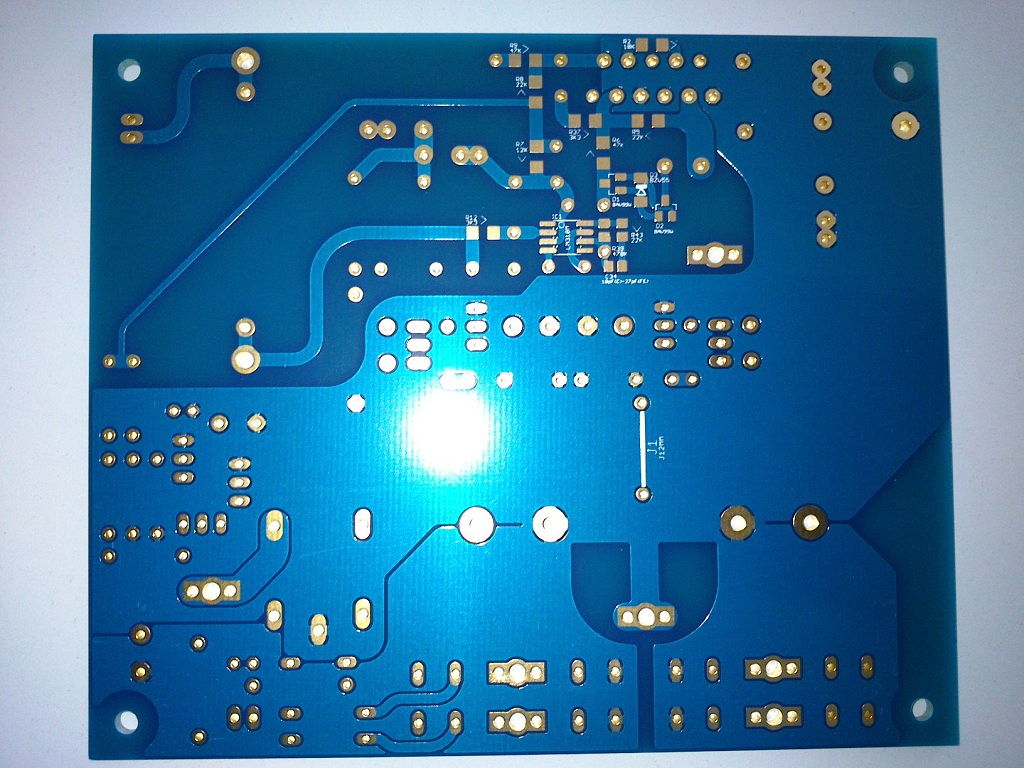
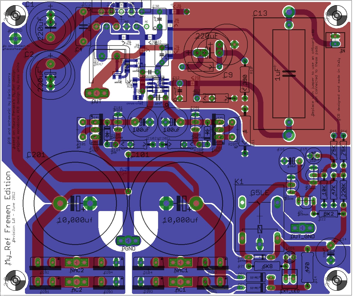
I've had a lot of fun designing my My_Ref variation which uses groundplanes and SMD components:
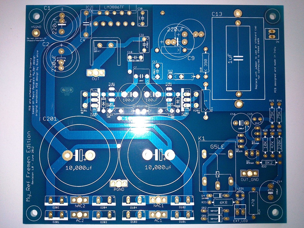
How it sounds?
IMHO great. 🙂
Also on the bench it fares pretty well (measures of beta boards by KSTR).
Using ground planes is useful for PS lines (lower inductance), helps to keep impedance more controlled (so less reflections) for signal traces...and if correctly designed makes the amp more RFI friendly 😉
Last edited:
Hi All,
I'm currently "fighting" to layout my two layer pcb correctly (thru hole design). Signals and power on top and ground in bottom layer.
I used star ground to link all ground traces. And also try to run ground under signal and power traces.
I have designed an audio pcb with faders, summing amps, etc but the mistake i did is that ground traces are a bit too thin. The same for the power supply: (too thin ground trace 1mm). This leaded to high supply noise. after correcting supply ground with thicker traces, noise was much reduced, despite not completely eliminated. Lesson learned.
Now that i'm reading about ground planes, it seems that these can simplify grounding: for instance: Up to today i use to run a ground trace in between two power decoupling capacitors, ok so far. Now, with a ground plane ¿no more need to trace a ground in between the capacitors? ¿ just connect them at the ground layer? This would mean that no more ground tracing is needed and i could connect any component at ground right at their place.....but... i also read about not to SHARE grounds...and maybe i read to much, from different points of view...
So to resume a bit for Audio analog designs working at maximum 500-600khz, I would need 3 layer PCB: TOP: Signals and power, MID: Ground plane BOTTOM: signals and other traces.
Any comments are wellcome,
Thank you very much,
JAY X
Last edited:
Again, ground/power planes are never a bad thing by themselves in general terms, as long as they are done right.
In the analog audio world we are often dealing with -100db distortion/noise spec, we can no longer neglect the impedances over the copper foils and their effects. Forget the name "ground" when designing a layout. We have to instead visualize and examine every and all current loops that share a common part of the conducter hence the resulted voltage drops over the impedance of that common path of the currents, and how these voltage drops can affect the operation of the circuit and by how much. From such a perspective, using planes are often thought to be more risky than not using them.
In the analog audio world we are often dealing with -100db distortion/noise spec, we can no longer neglect the impedances over the copper foils and their effects. Forget the name "ground" when designing a layout. We have to instead visualize and examine every and all current loops that share a common part of the conducter hence the resulted voltage drops over the impedance of that common path of the currents, and how these voltage drops can affect the operation of the circuit and by how much. From such a perspective, using planes are often thought to be more risky than not using them.
- Status
- Not open for further replies.
- Home
- Amplifiers
- Solid State
- Are ground planes in audio pcbs legit?