Hi,
as some may know, my BB50 has died on one channel (after misbehaving and tripping out my Delta monos).
Would someone be able to do a sort of VR type diagnosis of this unit - I.E. If I send you the schematic, would you be able to tell me where to measure? Once we identify the fault, then I will be able to replace the faulty component.
Please email me offline if you think you might be able to help.
Many thanks!!
Jon
Bump!
Just in case anyone missed this??
I am loath to start with the DMM in a random manner. Last time I did that, my D290 amp went back to ARCAM to get repaired!! 🙄
😀
Cheers
Jon
Just in case anyone missed this??
I am loath to start with the DMM in a random manner. Last time I did that, my D290 amp went back to ARCAM to get repaired!! 🙄
😀
Cheers
Jon
Thanks Ray,
I'll be there with my meter tomorrow.
I assume that we are talking about measuring the "hot" rca connection to earth (or is it measuring between hot and cold on the rca....)?
Jon
I'll be there with my meter tomorrow.
I assume that we are talking about measuring the "hot" rca connection to earth (or is it measuring between hot and cold on the rca....)?
Jon
Jon, I will give it a shot 😱
PM me the schematics.
PS I have a BB 500 so I will be interested to see schematics ...
Dave
PM me the schematics.
PS I have a BB 500 so I will be interested to see schematics ...
Dave
Dave,
the file ARCAM sent me did not include schematics, just some artwork showing where to add links for a voltage change...
Will detailed photos work, or measurements prompted by detailed photos??
Cheers
Jon
the file ARCAM sent me did not include schematics, just some artwork showing where to add links for a voltage change...
Will detailed photos work, or measurements prompted by detailed photos??
Cheers
Jon
Hot and cold on the rca.
Given that you have no schematic, perhaps you could post the chip line-up of the analogue and digital stages.
ray.
Given that you have no schematic, perhaps you could post the chip line-up of the analogue and digital stages.
ray.
Here is something I had prepared earlier.....
Hi Ray,
here's a thread I posted when I first joined the forums.
http://www.diyaudio.com/forums/showthread.php?s=&threadid=7118
It lists all the chips in the analogue and digital stages.
I have recontacted ARCAM and asked for the scemas that go with the Service Manual.
Thanks for your interest. 🙂
Jon
Dc!
I have now measured the DC at the offending channel RCAs.
12.4 Volts!!!!!!
Other channel is pretty much zero (measured on the 200mv scale).
Would this indicate a burnt cap? 😕
Cheers
Jon
I have now measured the DC at the offending channel RCAs.
12.4 Volts!!!!!!
Other channel is pretty much zero (measured on the 200mv scale).
Would this indicate a burnt cap? 😕
Cheers
Jon
If the output is AC-coupled i.e. the circuit has a dc-blocking cap on the output, then it could indicate a short across the output cap. If the circuit is DC-coupled, then you need to check the op-amps.
Trace the output back to the cap or op-amp and take it from there. If the circuit leads back to one of the NE5532's, measure the voltage on the power pins to make sure they are present, pin8 being positive and pin4 is negative. If they are both present measure the outputs, pins 1 & 7. They should be around 0volts.
ray.
jon, i agree with ray on checking out the 5532's (if they are driving the OP)
(from linked thread)
also try re-seating the daughter board, if it's removable, and any other connectors (particularly power)
dave
(from linked thread)
also try re-seating the daughter board, if it's removable, and any other connectors (particularly power)
dave
Oh yes, i just noticed ...
from the block diagram on the (pm'd) service sheet the OP has a servo and no cap
dave
from the block diagram on the (pm'd) service sheet the OP has a servo and no cap
dave
Hi Dave,
I have had the daughterboard out on a few occasions - I'll pull it again to take a couple of pics and be extra careful when I replace. The board is connected to the mail board by some risers.
More later, as The Boss has some jobs for me..........
Cheers
Jon 😀
I have had the daughterboard out on a few occasions - I'll pull it again to take a couple of pics and be extra careful when I replace. The board is connected to the mail board by some risers.
More later, as The Boss has some jobs for me..........
Cheers
Jon 😀
Possible fault....
Hi,
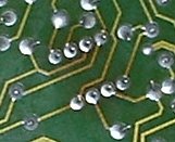
I was tracing back the RCAs and they go to the daughterboard. Everything looked good from the top, but as I looked underneath the pcb, I noticed some discolouration around where Z101 was soldered in. This is one of the 5532s.
I took some pics, but they are quite large - even after editing. I have the insides of the BB50, and mother and daughterboards.
I'll post them if you'd like a look. In the meantime, I'll attach a pick of the discolouration. It wasn't that easy to spot - but now I can make it out clearly.
It seens that the mainboard is purely to supply the power to the daughterboard, and that's where all the action takes place. ISTR that the daughterboards are interchangeable between Black Boxes, even though they used different DAC chips on them.
I'll have to get hold of a 5532, and then measure it (as I have the BB dismantled).
I'll let you know how I get on!! 😀
Cheers
Jon
Hi,
I was tracing back the RCAs and they go to the daughterboard. Everything looked good from the top, but as I looked underneath the pcb, I noticed some discolouration around where Z101 was soldered in. This is one of the 5532s.
I took some pics, but they are quite large - even after editing. I have the insides of the BB50, and mother and daughterboards.
I'll post them if you'd like a look. In the meantime, I'll attach a pick of the discolouration. It wasn't that easy to spot - but now I can make it out clearly.
It seens that the mainboard is purely to supply the power to the daughterboard, and that's where all the action takes place. ISTR that the daughterboards are interchangeable between Black Boxes, even though they used different DAC chips on them.
I'll have to get hold of a 5532, and then measure it (as I have the BB dismantled).
I'll let you know how I get on!! 😀
Cheers
Jon
Attachments
Sorted!!!!
My 5532Ns arrived this morning - I got a couple of spares because the originals will only be stocked at Farnell until supplies are exhausted.
A few minutes with the iron, and no DC at the RCAs. A quick plug in to confirm it works - and it does!!! 😀
Dave, Ray,
thanks very much indeed for your help in sorting this out. As an electronics newcomer, I learned some new and valuable techniques from this!
Cheers
Jon 😎
- Status
- Not open for further replies.
- Home
- Source & Line
- Digital Source
- ARCAM Black Box 50