I've just checked the more obvious general parts detail and marks, going off the PCB artwork which states "A&R Cambridge 1984" which should nail it down to the first, simply "Alpha" model. There's no date on the certification label though so it could have been assembled later as the serial number might suggest.So it is the original version and not the later one with DC servo and FET......
Unless Juanito can find other specific model details on the front or rear panel or perhaps another label inside the case, I can only assume that's what it is.
You should begin by using a bulb tester for the amplifiers safety.
Initial checks are to confirm the supply voltages are correct on the bad channel that has this 6 volts offset.
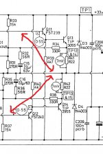
I would do a quick check initial check of the base-emitter voltages on the output and driver transistors as measured from the junction of the 0.22 ohm emitter resistors. Q13 base should show around 0.65 volt and Q11 should show around 1.3 volts as referenced to the 0.22 ohm junction.
Do the same for Q14 and Q12. The readings should be similar but this time a negative voltage.
Is the bias current correct as measured by checking the voltage across the 0.22 ohm.
Check that R21 and R30 have around 0.65 volts across each.
Check that the voltage on the base of Q2 is near zero.
NO speakers attached for any of this.
Initial checks are to confirm the supply voltages are correct on the bad channel that has this 6 volts offset.
I would do a quick check initial check of the base-emitter voltages on the output and driver transistors as measured from the junction of the 0.22 ohm emitter resistors. Q13 base should show around 0.65 volt and Q11 should show around 1.3 volts as referenced to the 0.22 ohm junction.
Do the same for Q14 and Q12. The readings should be similar but this time a negative voltage.
Is the bias current correct as measured by checking the voltage across the 0.22 ohm.
Check that R21 and R30 have around 0.65 volts across each.
Check that the voltage on the base of Q2 is near zero.
NO speakers attached for any of this.
Thanks mooly!
Sorry for the delay... done some testing this afternoon and these are the results:
Q13=0,54 v
Q113=0,53 v
Q14=-0,58 v
Q114=-0,57 v
Q11=0,52 v
Q111=0,52 v
Q12=-0,54 v
Q112=-0,54 v
R21=0,59 v
R30= 0,67 v
R121=0,58 v
R130=0,66 v
Q2=0,61 v
Q102=0,61 v
Hope this means something and THANKS again for your time!
Those readings show virtually identical results between the two channels.
One thing that seems wrong (even on the good channel) is that you measure only 0.52 and -0.54 volts on Q11 and Q12 base as referenced to the amolifier output.
You should be seeing twice that voltage between these points, particularly on the goood channel.
One thing that seems wrong (even on the good channel) is that you measure only 0.52 and -0.54 volts on Q11 and Q12 base as referenced to the amolifier output.
You should be seeing twice that voltage between these points, particularly on the goood channel.
Attachments
Sorry Mooly, I forgot to mention that both channels have the same DC offset at 6.* volts, after “rechecking” things I realised that both loudspeakers were going bad. That’s the reason I took data from the right channel too.
So, after this initial check what should I do next?
So, after this initial check what should I do next?
Last edited:
Having the same identical fault on both channels suggests a common cause. That's very odd... and this is not easy at a distance.
There is a possibility this could be caused by a problem with the FET muting circuit. Has Q1 in the preamp been replaced for something different ?
What is the DC voltage on the gate of Q1 ?
There is a possibility this could be caused by a problem with the FET muting circuit. Has Q1 in the preamp been replaced for something different ?
What is the DC voltage on the gate of Q1 ?
Most likely a cure for your problem. I have two Alpha Twos with the same issue. From switch on over about 20 seconds the voltage on the speaker sockets rises from 0 to approximately 6 volts ON BOTH CHANNELS. I.e. 6v dc offset with speakers connected (10V if there not). I spent hours trying to find the problem. Came back to them some days later and just by chance noticed on one of the amps that both the balance and treble controls were snapped where they connect to the pcb. On the other amp just the balance control. In other words the legs are soldered to the PCB with no damage to the board but the carbon tracks on the pots themselves on both channels are snapped across !! Look back at the pots from the component side of the board and you should see the problem. So no connections between the board and the controls. Ordering new pots provided a 100% full cure.Ov dc offset. A really weird fault.. The way the pots are mounted must put a great strain on the carbon tracs themselves. Some how them not being connected causes the amp to become unstable. Hopefully this will help someone
Best wishes
John.
Best wishes
John.
- Home
- Amplifiers
- Solid State
- Arcam Alpha problems