Hi all,
I have a 9 / 9p bi-amp set up with some Monitor Audio floorstanders. All has been well until suddenly last night the 9p went dead. I opened it up and the internal 230v mains fuse in the lower right corner had blown. There was a spare on the board, so I replaced it and it blew immediately again.
Can somebody give me some tips on where to go from here? I'm not an electronics guru, but I know how to solder and use a multimeter.
Furthermore, the "T1A6L" fuse as marked on the PCB, doesn't show up in Google. Does anybody know the spec for this fuse (it's a different socket for 230v and 115v - I need for 230v)? I think I'll have to buy a few replacements.
Thanks in advance.
T1A is just a 1A fuse.
These are notorious for blowing output transistors if the speaker leads are inadvertently shorted together.
Unfortunately output device failure also often causes the drivers to fail.
BUT, before we go down that route, can you see any bulging or leaking of the large PSU capacitors ?
These are notorious for blowing output transistors if the speaker leads are inadvertently shorted together.
Unfortunately output device failure also often causes the drivers to fail.
BUT, before we go down that route, can you see any bulging or leaking of the large PSU capacitors ?
Last edited:
Hi, thanks for responding. I've ordered some 1A 230V slow-blow fuses from Ebay.
As for the rest of your post, I don't see why the speaker leads would suddenly short together, the amp hadn't moved. And I don't know what you mean by output device failure - do you mean an amp failure might have blown my speakers?
Second post - the two massive caps aren't bulging or leaking. I'm not sure how else to "check" them with a standard multimeter. What part numbers on the schematic are the output mosfets, and how do I check them?
I get the feeling that I need a bit of extra hand-holding here, hope I'm not being too thick...
If anyone's still reading, I wanted to add that I took the spare fuse out of the integrated amp (1.6A by the way not 1A), disconnected the power amp from everything except the mains and... pop. So I know it's not the speakers (currently bi-wired to the integrated amp, all working okay).
So as I said above, I 'm not sure exactly *how* to test the caps and the four output mosfets with my standard multimeter. I hope I can do them in-circuit. On the bright side, I have locate the latter, they're the big ones attached to the heatsinks, right? 🙂
I don't mind buying some better diagnostic tools than my standard voltmeter if they aren't too expensive.
I seem to remember something from the past about disconnecting some of the transformer coils then switching the amp on to isolate the problem, any mileage in doing that here?
Hi,
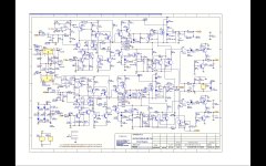
Normally when the main fuse blow most of the time there is a shorted in the rectifiers or in the main filter caps section. Check the caps + pos side to ground or the - neg caps to ground. Remembered that there are caps for the neg voltage and the pos it is grounded. If you have a low resistance reading means that you have a shorted. If you find that there is a shorted then by isolating each components one at a time you maybe able to isolate which one it is causing the short.The schematic does not shows the power supply components so I can not advices which components to check.
Normally when the main fuse blow most of the time there is a shorted in the rectifiers or in the main filter caps section. Check the caps + pos side to ground or the - neg caps to ground. Remembered that there are caps for the neg voltage and the pos it is grounded. If you have a low resistance reading means that you have a shorted. If you find that there is a shorted then by isolating each components one at a time you maybe able to isolate which one it is causing the short.The schematic does not shows the power supply components so I can not advices which components to check.
In this case it is likely that a MOSFET has failed short. Desolder the IRFP240 devices and test them. I guarantee you'll find one failed source to drain. Fortunately they are cheap.
JAYCEE - Looks like this guy needs a bit more guidance than just a description.
TOPPERDOGGLE - I'm agreeing with JAYCEE.
What you need to do is to remove Q1, Q2, Q101 and Q102. They are MOS-FET devices so are slightly sensitive to static discharge. Just make sure that everything is connected to EARTH, including YOU and the soldering iron.
If you place the IRFP240 onto its back, the left hand leg is the GATE, the centre leg is the DRAIN and the right hand leg is the SOURCE.
With a multimeter you should get very high reistance between the DRAIN and the SOURCE in both directions and you should get INFINITY OHMs between the GATE and both the DRAIN and the SOURCE.
If either reading is LOW then the device is SHOT.
Arcam don't usually use the TO3 version IRF240. I would have expected the TO247 Plastic version IRFP240.
IRFP240s are cheap. Try Cricklewood Electronic, Farnell or even RS. Cricklewood have them for £2.50 each.
JUST BEWARE. If you do find that one of the output devices have a short circuit on its GATE then it will probably have taken out is driver transistor in the process.
These MOS-FET amps rely upon the GATE insulation resistance to keep the GATE current low so-as to reduce the dissipation in the drive circuitry.
Last edited:
Thanks people. I'll have a crack at testing these guys over the weekend. I'm assuming I have to desolder them i.e. I can't test them in-circuit?
As for the possibility of the driver transistor being shot, I'll test these four first then come back on that if necessary. 🙂
As for the possibility of the driver transistor being shot, I'll test these four first then come back on that if necessary. 🙂
Yes you must desolder them to be sure. Before you test, short the Gate pin to Source - MOSFETs are fairly easily turned on (ooer) and its possible to get a false reading. If you get zero resistance both ways between source and drain, or a reading between Gate and Source or Drain, it's shot.
Wow, you people are just great. I desoldered Q1, Q2, Q101, Q102 as per advice (after removing the heatsink, yes the brain engaged in the end 😉 ).
It turns out that Q1 and Q2 look solid, and Q101 and Q102 are both shot. I'm not sure if it's normal that both would blow at once, bear in mind as explained above I did replace the fuse once and turn it on again, just to see if it was a random thing.
So, what next? Various questions I'm pondering:
1. Should I replace all four as a matter of course? I don't know what the failure mode is. If it's time / wear-related, then I probably should. If it's something else, how do I find out what caused them to blow?
2. As for causing drivers to fail when blowing, what else should I test? Do I have to now test other transistors in the same way, and if so, which ones according to the schematic? Or do I have the wrong end of the stick? Do driver transistors *always* blow when output ones do, or is it pot luck?
3. Is there anything else in general that I should consider?
Again, thank you all for your help so far, I don't have a massive budget so without your help, the amp would have been on the scrap heap, which would have saddened me immensely.
Replace all four. You should check Q3, Q4, Q5 and Q103, Q104, Q105.
It is not really time related wear. I've seen mains spikes kill a 7R amp which is a similar circuit. If Arcam had fitted a MOV/Tranzorb type device across the transformer primaries it'd probably help. Also if they had fitted catch diodes across the MOSFETs...
Make sure you renew the insulator pads and grease when you fit new MOSFETS.
Full service manual here: Arcam Alpha 9 | Owners Manual, Service Manual, Schematics, Free Download | HiFi Engine
Okay, I tested Q3-5 and 103-105, all okay, soldered them back in. I'm going to order the four replacement MOSFETs and cross my fingers! 😉
Thanks so much for the assistance so far, I'll post again when I've tried the new MOSFETs (for better or for worse...).
Thanks so much for the assistance so far, I'll post again when I've tried the new MOSFETs (for better or for worse...).
The guy in the shop told me the IRFP240 is no longer in stock but he sold me 4x IRFP250s which he said are the same spec apart from maximum current. Can someone confirm that they will work before I get the soldering iron out?
Hmm, maximum current increase is due to lower RDS(on) value. On the other hand they have more capacitance and are slower as a result. If you were using them for just plain power switching it would not be a big deal, but in an audio amp I would try and get the IRFP240. I could not say for certain whether the 250's would be stable.
I think IR might have discontinued their version but the part is second sourced. CPC stock Vishay's version here:
VISHAY SILICONIX|IRFP240PBF|MOSFET, N, TO-247AC | CPC
I think IR might have discontinued their version but the part is second sourced. CPC stock Vishay's version here:
VISHAY SILICONIX|IRFP240PBF|MOSFET, N, TO-247AC | CPC
Just a message to say thanks to those who helped. I now have a working 9p again, and it sounds great. You stopped it being thrown on the scrap heap. Happy new year all! 🙂
....and a thanks from me too...in 2020!! 🙂
I've the same problem with an Alpha 8R amp.
I've removed/tested/replaced the 4 large rectifier diodes, and reservoir caps...all appear OK.
Used DMM to test Q1, Q2, Q101, Q102.....but did this IN SITU.
All 4 of 'em appear to be OK, as they behave identically in terms of meter readings.
So...I must remove these before testing to get a real reading!!?
Went ahead and removed 4 x IRF540 MosFets.
A bit confused here....all behaved same....but showed the same High Resistance (3Meg Ohm +) in ONLY ONE DIRECTION. (this being SAME DIRECTION)
Additionally....with the MosFets removed...the unit goes through standby/power on without blowing internal fuse.🙂
A bit confused here....all behaved same....but showed the same High Resistance (3Meg Ohm +) in ONLY ONE DIRECTION. (this being SAME DIRECTION)
Can this be de-mystified???...........
With a multimeter you should get very high resistance between the DRAIN and the SOURCE in both directions ..........
Additionally....with the MosFets removed...the unit goes through standby/power on without blowing internal fuse.🙂
Testing FET's can give unexpected results because the gate is high impedance and can literally float to a voltage that can make the device conduct.
They should read like a diode between Source and Drain (showing around '600' on a diode range on a DVM) when the red meter lead is on the Source. Reverse the leads and it should read open circuit on the diode range.
On ranges other than 'Diode Check' its all meter dependent and results are open to interpretation.
Power FET's usually fail by going short circuit between D and S which would show as a simple continuity test. If all your four devices test the same they are going to be OK imo.
- Home
- Amplifiers
- Solid State
- Arcam Alpha 9p blowing fuse