Hello,
I have posted this in relation to the Alpha 5, but it probably applies to many other amps.
I have just replaced the blown SMF045 Mosfets for IRF540Ns on one channel and set up IQ on both channels for 4mv across R1 and R101 as per service manual and amp works fine but I am concerned about the power supply voltages (and why Mosfets blew in the first place). Please can anyone advise or assure me.
My mains voltage is 249 AC which results in transformer output of 29.3-0-29.3 AC. After rectification and smoothing this becomes +39.1 and -39.1 against the service manuals indicated +37 and -37.
Regulated + 15.1 and - 14.7 volts for the preamp and tone stages are provided by 7815 and 7915 regulators with no heat sinks which are running very hot. The inputs to these are +34.3 and -34.7 which seem uncomfotably close to the 35v limits. Should I be worried or is this within normal design tolerances?
What you observe is typical of a lot of consumer electronics... it all comes down to cost.
The input to the regulators is near the limit but on the up side the current draw in this application is low. There is little you can do without modifying the design... just check the regulators for any dries because heat does tend to encourage solder joints to fail on hot running parts.
The main rails being a little high is absolutely no problem to FET's. Again I would check for dries on any hot running transistors in the driver stages and VAS stages of the poweramp as anything like that could be a cause of failure of the output devices.
It is also possible for any hot running transistors to fail intermittently (typically going open circuit base to emitter momentarily) and again that could cause output stage failure.
So a few unknowns, the FET's in themselves should be 100% reliable in normal use and so you have to ask whether anything contributed to their demise.
Thank you very much Mooly. I did find the IQ high after replacing the Mosfets, so maybe there was thermal runaway. I will check the joints on hot components as you advise. Now I am assured about the voltages, I will give it a good soak test and see. I did buy a couple of extra Mosfets.
It is worth looking for dries, look very closely for any cracking around the joints. Look at the last two images in post #1 here for examples:
Sony CDP790 and KSS240 Restoration Project
Sony CDP790 and KSS240 Restoration Project
I'd be worried, too close to the limit, unwanted thermal stress.Regulated + 15.1 and - 14.7 volts for the preamp and tone stages are provided by 7815 and 7915 regulators with no heat sinks which are running very hot. The inputs to these are +34.3 and -34.7 which seem uncomfotably close to the 35v limits. Should I be worried or is this within normal design tolerances?
Perhaps you can drop the voltage down with some fairly chunky zeners or even dropper resistors (values to be determined by measuring the current draw). And any heatsinking is better than none if there's room to fit some.
Hi Mark,
Thanks for your reply too.
There was already a dropper in place. 3 x 470 ohms fusible resistors in parallel. Current through these measured 32 mA, so I disconnected one of them. Now my 15v regulator inputs are a more comfortable +31.8 and -32.6. I also added some DIY aluminium heatsinks and the regulators are running much cooler (I can now touch them!). The dropper resistors get slighty warm. I resoldered all the transistors in driver stages.
Thanks Mark and Mooly.
Pleased to hear its all working 
Removing one of the 470 ohms is fine for the regulators but you need to be sure the dissipation in the resistors isn't to close to their rating now. The reduction in voltage at the reg has now shifted to across the resistors. The series current (total current) is still the same but now split between two instead of three.
Removing one of the 470 ohms is fine for the regulators but you need to be sure the dissipation in the resistors isn't to close to their rating now. The reduction in voltage at the reg has now shifted to across the resistors. The series current (total current) is still the same but now split between two instead of three.
I replaced the 3 x 470R resistors in mine with 7824 / 7924 regulators. Much better solution. These regs do not perform well when dropping 24+ volts in-to-out.
Mine also had no-name 7815/7915's which I replaced with NatSemi parts (this was 10+ years ago).
Mine also had no-name 7815/7915's which I replaced with NatSemi parts (this was 10+ years ago).
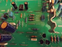
32mA with max drop of 7.4v = 236mW across the two 470R. One resistor may be carrying more load than the other so its pushing the limit if they are 1/8 Watt resistors but I think they are 1/4 Watt. Photo attached.
Will see how it goes. 🙂
I like the two stage regulator approach suggested by jbau but surely we have still got the max voltage input limit problem for the 7824 and 7924.
Will see how it goes. 🙂
I like the two stage regulator approach suggested by jbau but surely we have still got the max voltage input limit problem for the 7824 and 7924.
Attachments
It is near the limit but as I mentioned before, the current is very low which gives the regulators an easy time. 24 volt regs splits the dissipation between the two.
Another option could be to use a series Zener. A 10 volt Zener would dissipate under 0.5W.
Remember though that all these options lose the safety option the fusibles give. What would happen if a short occurred on the rail.
Another option could be to use a series Zener. A 10 volt Zener would dissipate under 0.5W.
Remember though that all these options lose the safety option the fusibles give. What would happen if a short occurred on the rail.
A 5W Fusible will run cool, use it to start supply from the 35 volt rail, then feed the regulators...how does that sound?
And from 470R, try a 1K or even 1k5?
3 x 470 in parallel is only about 150 to 160 R...
You need to feed the 15 volt regulators at least about 3 volts higher than output volts, so you can select a resistor value, and use a fusible for safety...is that okay Mooly?
And space permitting, put heat sinks on the regulators, simply good workman practice
Last edited:
I like the two stage regulator approach suggested by jbau but surely we have still got the max voltage input limit problem for the 7824 and 7924.
I've had them in my A6 and my son's A5 since 2009 without issue. And without adding heatsinks. It is by far the best-sounding approach. Consider the impact on output impedance of the 15V regs that each approach has. These regs work best when dropping only 3-4 volts.
- Home
- Amplifiers
- Solid State
- Arcam Alpha 5 Power supply query/concern