Sorry i was very tired last night, I seem to have confused myself. Yes Z3 and Z4 is on the underside of the mainboard near the terminals. I have replaced all the caps except the non-polars, but those ones all ESR really good. Carefully went over the underside and touched up any joints. will put it back together later and test again, but not confident it will start working normally. Still a mystery about the absent Q59f if someone can let me know if that should be on on the power amp version as well as the integrated could they let me know. Thank you for all your help so far people, you have been brilliant.
I just swapped the pre amp board from another unit. Still no sound on the left channel. super confused??? Could it be in the front PCB?
Okay my little oscilloscope arrived yesterday. so i did some testing. I used a 1khz signal from cd player as a source. First i started where the connector go's from the pre-amp to the mainboard. I have my sine wave on the right but not the left. I also have my +- 15volts. Then i went to the Lm1972 in1 19mv out1 8mv in2 205mv out2 10mv. Still no left channel signal detected.
It seems your problem is in the power amplifier section.
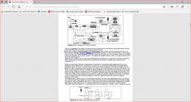
In this the feedback divider network sets the closed loop gain R170 (22K)/R164 (560R) which works out to 1+22,000/560 = 40.3
This type of system will amplify down to dc as R164 connects to ground. There is half a TL072 Z3A acting as a servo to offset any dc offset drift.
If there is a cold solder join which has increased the resistance in the connection between R164 and ground this will reduce the gain of the system. If there is no connection at all the gain will reduce to 1. You should also check for continuity between R170 and R164.
Hello mjona, Are we talking about the 10p power amp that has 390mv problem or the integrated version that has the left channel missing? If it is the integrated i fixed that yesterday.
Hello mjona, Are we talking about the 10p power amp that has 390mv problem or the integrated version that has the left channel missing? If it is the integrated i fixed that yesterday.
The service manual I looked at is that shown at HiFi Engine and this is the same for 10 and 10p which suggests the part numbers in either would be the same on the power amplifier boards in both cases.
My focus was on a possible reason for your problem with the missing channel. My supposition is that the gain of this could be down to 1 while the active channel gain is 40.
If you disconnect the right channel from the speaker and wind up the volume on the left channel you might be able to hear some sound at a very low level from the left speaker up close. If that is the case you should investigate along the lines previously advised.
While what I have outlined is theory - this has been the correct diagnosis in some repair work I have done.
Last edited:
Thanks mjona, you sound like you have had a great deal of experience but like i say that issue is now repaired. But i wonder if you could help me with the 10p issue? I was wondering if i just change both Z3 and Z4 and Q22 and 29 it might solve my high mv problem, what do you think? Thanks.
From your description in post 13 on page 5 - I think it more likely your problem is due to an inordinate delay in the charging of a capacitor somewhere in the circuit.
One that is leaky or has a high resistance solder join in a part of the circuit shared by both channels would impact on both - this might be a process of elimination - starting with inspecting the work that was done by the previous owner.
The op.amps that control the servo and bias are derived from Z1 and Z2.
Do the supplies to the supply pins on Z3 and Z4 rise to + and - 15 volts at the same rate?
As far as the servo's Z3A and Z4A are concerned there is a time delay for C71 and C73 to be charged from the output terminal via R176 and R178 so there would be some delay in stabilising the dc offset - so indications this is functioning but under severe handicap.
Hi mjona all the caps were changed for Nichicon Pw, except the non-polar, main filter caps and the 100v 100uf ones. But they ESR really good. Went over the solder joints very carefully touching up anything suspicious, but that does not mean i did not miss anything. I will have to work out a way to measure what you say because it is all underneath. No helpful flap. If i do would my multimeter and oscilloscope together give an adequate result or will i need two multimeters? Thanks
Also do you mean Z3C and Z4C on the schematic?
These are also perform a servo function in monitoring the standing current at the output. The feed circuitry for these is separate in each channel.
The changing of servo caps can give rise to switch on problems at the output. I can see there are relays to switch the outputs to the speakers.
The switching action should be delayed until the dc and output Iq have reached their respective points of equibrium.
I imagine that should take only a few seconds and the level of dc would not activate the protection to prevent the relays engaging - you mentioned Z5 had been changed?
Yes i replaced Z5 the 8v regulator because someone had removed the heatsink and i was not sure if it life may have been reduced because of it. Thanks.
as small digression:
My Arcam was outclassed in every imaginable way by a simple (albeit of 1st world origins) ' inexpensive' Lm3886 chip amp.
I was completely gobsmacked by the sounds improvement. Haven't used the Arcam since.
as a wee heads up; Imo you are beating a dead horse.
My Arcam was outclassed in every imaginable way by a simple (albeit of 1st world origins) ' inexpensive' Lm3886 chip amp.
I was completely gobsmacked by the sounds improvement. Haven't used the Arcam since.
as a wee heads up; Imo you are beating a dead horse.
I would have to here that to believe it. I am extremely fussy. How much is the cost of one of those?
Yes i replaced Z5 the 8v regulator because someone had removed the heatsink and i was not sure if it life may have been reduced because of it. Thanks.
In my last post I should have said the charging of servo caps not the changing thereof.
What sort of time does it take for the dc at the output to be corrected on power up and what is happening to the input and output voltages on the dc servo op.amps during this process - Is it safe to assume the input and outputs are in synch.
The bias servo monitors the output current in one half of the output stage and there is a bootstrap capacitor which needs to be charged in the other half. Z8A -Z8C in one package are involved in the bias function.
The part of the diagram near Z8C mentions "power off auto bias defeat" there could be a problem with this section powering up due to say C16 being leaky and the associated circuitry interpreting a charging delay as being due to switch off.
C16 a 10uf 50v cap? was changed also. The units behaviour did not change after recapping.
I assume you would have replace C15 also there is a label "Fault" in this area of the schematic that connects back to the display PCB - is there a corresponding LED that lights up during the turn on period?
Yes C15 was replaced. There is no other led just one press power, Led is amber for three seconds then it turns green as the speaker relay kicks in. No fault indicated. Also remember this is the power amp version, so no display.
I would have to here that to believe it. I am extremely fussy. How much is the cost of one of those?
Doubting Thomas ? Well My friend you are in for a Serious Epiphany..., IF
willing to suspend your trust in Brochure Babbles.
Paid ~100$ for mine which was a replacement circuit/kit for an aged Dynaco St120 (updatemydynaco.com) Everything 'cept the transformer.
There are even.. Far better.. LM3886 ones available currently.
Hunt up: Modulus-86 Rev. 2.0: Composite amplifier achieving 0.000067 % THD.
NO exaggerations involved /intended.. the Arcam is erm.. Crap sounding.. Once you move up/into genuine quality electronics.
One has to have enjoyed the Kool Aid to believe otherwise.
Hey! I paid Full retail price for my Arcam (multiples of the simple lm3886 gizmo).. imagine how pissed I was.
That said; a subsequent Pass Firstwatt F6 (diy build). which uses the Very Same Output devices as the Arcam.. Amazing what a 'World class' designer was able to make them perform/sound like.
Compared to what the obvious Bunglers at Arcam managed.
F6 was as big a step Up from the Lm3886 amp as the lm 3886 amp was from the now complete Garbage sounding Arcam
Last edited:
- Status
- Not open for further replies.
- Home
- Amplifiers
- Solid State
- Arcam Alpha 10 Very low sound on the left channel..Help please.