I'm mucking around a bit with an A75 that a buddy brought over. Physically everything looks perfectly great inside this amp. Nothing is burned, no zener diodes are amiss, all the lights do that they are supposed to, but this thing only makes about 2W into 8 ohms at 0.1%THD/1kHz. Oddly the performance of the amp gets better at low frequencies, and it just about does its rated power at 100Hz.
I have adjusted the bias to 15mV, temporarily tacked in new PSU caps, reflowed the solder joints on the output devices, and I split the pre/power sections and verified that the preamp section isn't causing problems. At this point it's both channels of the amplifier that both have the exact same problem. Other than some power supply parts, I'm not seeing a whole lot that's shared between channels. All the voltage checks listed in the service manual are OK and the 2W the amp puts out sound decent.
I'm trying to do as little work to the board as I possibly can since it's single sided and rather sensitive, so I'm hoping someone has experience with this particular issue.
So perhaps the slew-rate is being limited by some failed component (same each side perhaps due to same overload event). Perhaps the input stages are starved of bias?
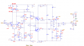
Here are the DC voltages for one channel.
All the active devices "after" the output devices don't appear to be doing anything, but they also don't look like they should be conducting.
The collector current for Q719 and Q718 looks too low to be correct, but I've been wrong before!
All the active devices "after" the output devices don't appear to be doing anything, but they also don't look like they should be conducting.
The collector current for Q719 and Q718 looks too low to be correct, but I've been wrong before!
Attachments
This looks like a job for an oscilloscope, in order to define the frequency roll-off and point to the likely suspects, as Mark suggests.
With the feedback loop in place, there isn't anything detectable as roll-off, just distortion with rising frequency (to a point at least).
When I attempt to open up the feedback loop so I can start tracing signal through the amp, it kicks on the protection circuit.
How would you guys proceed?
When I attempt to open up the feedback loop so I can start tracing signal through the amp, it kicks on the protection circuit.
How would you guys proceed?
Well, it looked like I could just pull the output devices and the amp would be happy enough to keep running, and that would also remove the feedback loop, so that's what I did.
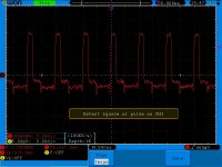
Here is the collector of Q619 trying to play a 1kHz sine wave. What's rather odd is that at lower frequencies it looks equally garbagy.
Here is the collector of Q619 trying to play a 1kHz sine wave. What's rather odd is that at lower frequencies it looks equally garbagy.