Guillermo,
there are two capacitor critical in your amplifier, c2 and c3, and the sound depends by they. An upgrade should be made changing these cap with very low inductive caps like rubycon very hight speed series. For c2 you can use a 47uF 50V or more , up to 220uF 50V, if this cap is a very speed.
there are two capacitor critical in your amplifier, c2 and c3, and the sound depends by they. An upgrade should be made changing these cap with very low inductive caps like rubycon very hight speed series. For c2 you can use a 47uF 50V or more , up to 220uF 50V, if this cap is a very speed.
Hi Andrew T.
Q14 in schematic of the post nº1. (current source Vas).
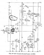
C2 and c3 in schematic of the post nº15. (c2 Tail current source, and c3 feedback a GND).
Q14 in schematic of the post nº1. (current source Vas).
C2 and c3 in schematic of the post nº15. (c2 Tail current source, and c3 feedback a GND).
yes, but where is it located?GEirin said:Q14 in schematic of the post nº1. (current source Vas).
Oh,GEirin said:C2 and c3 in schematic of the post nº15. (c2 Tail current source, and c3 feedback a GND).
not on topic then!
Yes ,
Q14 in Arcam A60 .
C2 and C3 in Philips 50W.
C2 are bipolar electrolitic and 47uF 50V , you could avoid other type.
C3 hight speed 470 uF 16V, electrolitic non-polarized, or two bipolar electrolitic in series with positive terminal united among them
Q14 in Arcam A60 .
C2 and C3 in Philips 50W.
C2 are bipolar electrolitic and 47uF 50V , you could avoid other type.
C3 hight speed 470 uF 16V, electrolitic non-polarized, or two bipolar electrolitic in series with positive terminal united among them
regarding c27 in arcam A60 it's used like frequency compensaton cap, many engineers think it's a bad method, but I have used this system in a preamp that actually I have designed and made.
I think that is a good way to compensate an preamp or amp. Infact, several friends of mine have request to me the PCB for making my preamp.
I think that is a good way to compensate an preamp or amp. Infact, several friends of mine have request to me the PCB for making my preamp.
Hi Pier Paolo.
I have decide to improve my old amplifier.
Please, look other thread "No Miller cap, double boostrapping amp"
Cheer
Guillermo
I have decide to improve my old amplifier.
Please, look other thread "No Miller cap, double boostrapping amp"
Cheer
Guillermo
Dear big jim
first thank you for your email. could you kindly tell me why the 2n3055 wont fit for Arcam A60?I think most NPN power BJT are fit for Arcam A60,such as MJE15003,2SC5200¡¢MJ480£¬ of course include 2N3055.
first thank you for your email. could you kindly tell me why the 2n3055 wont fit for Arcam A60?I think most NPN power BJT are fit for Arcam A60,such as MJE15003,2SC5200¡¢MJ480£¬ of course include 2N3055.
Hi all,
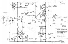
I woud propose these changes to Gulliermo's amplifier, they are showed in the photo.
1. the RC group I have added to schematic reduce the global feedback ratio to around 26 dB. This feedback network is well knowed from stasis amplifiers , but in these amp the global NFB is reduced to zero. In the Gulliermo's amplifier isn't possible reduce to zero the global NFB because it hasn't the many pairs of power bjts in the out like the stasis amplifiers have (or had).
I this moment I forgotten that a similar network is been used in some (or several.......) Nakamichi amplifiers.
I have studied very much the Gulliermo's amplifier and I think this is a very strategic but simple mod.
2. the other changes are:
tr7=tr8=mj15003 or mj15023
tr1=tr2=bc557b or bc556b
c2= 47uF 35V or 50V hight speed series bypassed with 22nF 50V cap
c3= 470uF 16V no polar electrolitic bypassed with 22nF 50V cap
3. change the c2 with a zener 16V 1/2W and in this case the r2=4,7k 1/4W and R3=10K 1/4W
Hi posxia
the 2n3055 case style =TO3
And the case style for the TIP3055=TO220 theres no room on the
heatsink.
all the best. jim
the 2n3055 case style =TO3
And the case style for the TIP3055=TO220 theres no room on the
heatsink.
all the best. jim
- Status
- Not open for further replies.
- Home
- Amplifiers
- Solid State
- Arcam A60