Hi Anadigit,
Can you tell me how do you connect the feedback with Hammond 1650P?
The schematic displays the feedback with R5 and R6. But on 1650P, both 4Ohm and 8Ohm connections don't allow feedback with 16Ohm.
Thank you in advance.
Can you tell me how do you connect the feedback with Hammond 1650P?
The schematic displays the feedback with R5 and R6. But on 1650P, both 4Ohm and 8Ohm connections don't allow feedback with 16Ohm.
Thank you in advance.
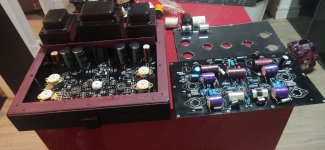
I'm trying to figure out if I mount some of the power supply components on the under side, if I'll be able to install the board just below the top surface of the chassis. The little heat sink looks like it could be reversed.
I just contact them and they have sold all VT60 PCB and there will no other. They don't want to sell data to make it.
So I decided to do my own. There is component side of PCB on arcdb website :
ARCDB - VT60
Anadigit, do you have picture of solder side ?
Thanks,
Sébastien
Last edited:
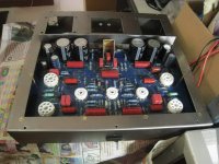
Finaly I made my own !
I made some change :
- a 10R resistor in each 6550 cathode
- each power tube has an adjustable bias

I made some change :
- a 10R resistor in each 6550 cathode
- each power tube has an adjustable bias
Last edited:
It is very unlikely the ccs is a bipolar anyway.
The transistor is supposed to be a MOSFET. VT100 schematic will display an example.
I use a depletion mode fet. In my PCB I put 4 pad SGDS to be able to try different fet.
I found BSS129 and DN2540 who has enough Idss Vgds and power dissipation. There is probably some others. I would like to found in 2SK family but without success...
I found BSS129 and DN2540 who has enough Idss Vgds and power dissipation. There is probably some others. I would like to found in 2SK family but without success...
Dear Cloners,
I would like to copy this apmlifier for my father's birthday. Just dont have enough time to design the pcb. Could you help me, with sending pcb files? I would be really appriciate!
Thanks a lot for Your help!
Good luck form Hungary!
Greg...
I would like to copy this apmlifier for my father's birthday. Just dont have enough time to design the pcb. Could you help me, with sending pcb files? I would be really appriciate!
Thanks a lot for Your help!
Good luck form Hungary!
Greg...
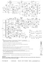
VT60 schema
Dear Antonytls!
I ask help if somebody has the conceptual drawing of the pcb, a component for this with values, I need him.
With thanks
appme
Dear Antonytls!
I ask help if somebody has the conceptual drawing of the pcb, a component for this with values, I need him.
With thanks
appme
Hi everybody! I am repairing my VT-60 and decided to go full mod. Do you guys still have the schematic and parts list for this version? Would anyone help me out and PM me? I have some doubts. It´s almost finished! Thank you!Finaly I made my own !
I made some change :
- a 10R resistor in each 6550 cathode
- each power tube has an adjustable bias
Attachments

VT60 schema
Dear Antonytls!
I ask help if somebody has the conceptual drawing of the pcb, a component for this with values, I need him.
With thanks
appme
Mr. Appme! Are you still enjoying your VT60? Have you compared to the original? How would you describe the sound?
Would you help me with the schematics and parts list?
Thanks!
Caution:
The schematic, Post # 1, shows 6550 on Fixed bias, and g1 Rg resistors are 160K.
That is easy for the phase-inverter/driver to drive.
But . . . The maximum Rg for a fixed bias 6550 is 50k.
Be prepared for one or more of the four 6550 tubes to go into Thermal-Run-Away.
Ouch!
You can not change the 160k resistors to 50k, because . . .
The phase-inverter/driver will distort, and might not have enough voltage swing to get max output power from the 6550 tubes (their needed g1 voltage swing).
Check all the other schematics, if one of them has Rg = 50k then you are OK with that version schematic (in regards to thermal run away).
Ah, an easier and more elegant solution:
KT88 maximum Rg, with fixed bias: 100k (most tube data sheets)
Better Yet . . .
JJ KT88, maximum Rg with fixed bias is 220k, If you limit Wa+Wg2 to less than 35 Watts.
If a JJ KT88 plate + screen dissipation is less than 35 Watts, Rg 160k is adequate.
Thank you, @6A3sUMMER ! In fact I had Antony´s version made. For some reason I didn´t notice the CCS o the right and since I´m following a mix of the original parts list and the mods that I made + the recomendations and discussions here, I got a bit lost in this specific area of the PCB. That´s why the schematic and parts list would help me a lot. I.e: Which transistor is used in Q2? A LM317?
Ah, a little plot twist: I drive my VT-60 with EL34s. That´s how I entered the magic DIY world.
Ah, a little plot twist: I drive my VT-60 with EL34s. That´s how I entered the magic DIY world.
Last edited:
Getting answers on what parts, and what parts values to use . . .
Requires that we know what else you are changing . . .
A 6550 is one thing.
An EL34 is another thing.
There are lots of changes that probably need to be made in order to have:
Reliability
Good, if not optimal Performance.
Plug and Play
Or,
Plug and Pray
Requires that we know what else you are changing . . .
A 6550 is one thing.
An EL34 is another thing.
There are lots of changes that probably need to be made in order to have:
Reliability
Good, if not optimal Performance.
Plug and Play
Or,
Plug and Pray
I'll save those words. They apply for a lot of situations in life.Plug and Play
Or,
Plug and Pray
As I said, I'm not coping and pasting things. I'm trying to learn and understand everything I'm doing. Although getting the parts list and schematics for this specific board won't be a fast shortcut, it will help me to understand their choices so I can make my own.
As you said, my VT60 is another beast and a little help on this Journey would be great.
Thanks for the advice!
Oh, let me tell my story in a few words. Bought this amp about 7 years ago. Met a tube fanatic (more than 20k tubes at his apartment) that became a close friend. He helped to mod the VT60 and taught me the little I know about tube amps. Unfortunately he passed away. Right after that, my VT60 was hit by two power surges (a natural and and a stupid me one). The PCB was gone. So I decided to rebuild it.
And here I am.
Sorry for the long post!
Last edited:
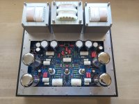
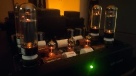
@geladk , thank you so much! It will help me a lot! It´s interesting to see that are many versions! I´m happy that this topic is open again. It would be interesting to know the results from different projects. This was my VT-60 two years ago:
Attachments

- Home
- Amplifiers
- Tubes / Valves
- ARC VT-60 Cloned :-)