First stated:
Myself am the DIY amateur, does not have any trade, the advertisement intention.
Tests PCB to be possible free to give the fellow friends, if certainly you are willing to pay express expense.
Myself am the DIY amateur, does not have any trade, the advertisement intention.
Tests PCB to be possible free to give the fellow friends, if certainly you are willing to pay express expense.
Explained:
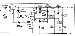
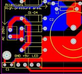
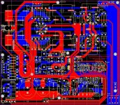
1) negative voltage for filament power supply.
2) outputs with IC (555) makes the time delay.
3) the more perfect grounding network.
1) negative voltage for filament power supply.
2) outputs with IC (555) makes the time delay.
3) the more perfect grounding network.
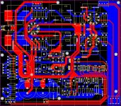
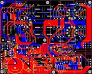
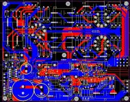
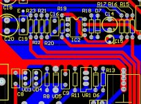
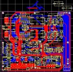
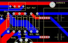
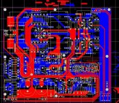
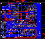
Diy M7 PCB
Hi
..
I had m7 pcb design in the early months.
Seems to be different versions. If friends are used to the original.
I think editing is available 1 to 2 points.
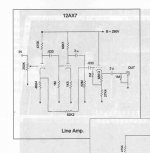
It is a Line Amplifier.
..
Good Luck
pramote😉
Hi
..
I had m7 pcb design in the early months.
Seems to be different versions. If friends are used to the original.
I think editing is available 1 to 2 points.
It is a Line Amplifier.
..
Good Luck
pramote😉
Attachments
Hi
..
I had m7 pcb design in the early months.
Seems to be different versions. If friends are used to the original.
I think editing is available 1 to 2 points.
It is a Line Amplifier.
..
Good Luck
pramote😉
Thank you!
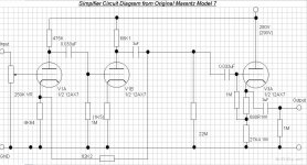
I don't understand the fascination with this design, it is NOT a good design. Much better has been done in the mean time.
Two VA stages and gobs of negative feedback with a feeble CF where just a single stage implemented with the appropriate tube would suffice.
My very first mistake when I started to experiment with tube audio was to build a clone of the ARC SP3A which you guessed it - is an early derivative of the 7. It was almost the last tube thing I built, I very learned quickly and designed something better.
Not trying to rain on your parade, oh all right I am.. 😀
BTW did you know that C as in "7C" stands for nothing more than cabinet?? There were two sevens, the tubed "7" and the "7T" which was transistorized.
Certainly influence of first transistor amp fashions smells through this tube schematic...
But it is one of ways to go: huge extra gain and deep negative feedback.
But it is one of ways to go: huge extra gain and deep negative feedback.
Certainly influence of first transistor amp fashions smells through this tube schematic...
But it is one of ways to go: huge extra gain and deep negative feedback.
Hi Wavebourne,
I had not really thought about the transistor connection, but I think you make a good point as this is a feature of a lot of hi-fi that arose during the very early years of the transistor in commercial audio use.
Good static measurements were assured through the use of lots of open loop gain thereby allowing massive amounts of negative feedback to be applied, that it sounded appalling on music didn't matter because Hirsch & Houck Labs said if it measures good it will sound good.. 😀
Last edited:
Certainly influence of first transistor amp fashions smells through this tube schematic...
Hmmm, not so sure. This is almost the same as the old Dynaco designs stretching back to the pre-transistor PAM1. Marantz just added a lousy CF to complete the package. The second stage is particularly poor- is the 68k plate resistor part of the original circuit?
Less open loop gain than you'd think here, so the feedback isn't terribly high.
Hmmm....
Attachments
Last edited:
http://i9.photobucket.com/albums/a78/Bob01605/DynacoPAM-1schematic.jpg
1959. You weren't even alive then. 😀
1959. You weren't even alive then. 😀
http://i9.photobucket.com/albums/a78/Bob01605/DynacoPAM-1schematic.jpg
1959. You weren't even alive then. 😀
I was 2 years' old! 😀
I built my designs from small wooden blocks then. 😉
- Status
- Not open for further replies.
- Home
- Amplifiers
- Tubes / Valves
- ARC Power source+Marantz 7C(PCB edition)