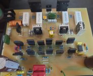
Assuming only Q19-Q22 are present, my suggestion would be to temporarily connect the "output" buss of all those 0.33 ohm resistors to the emitter of Q19. This will provide a feedback connection to R27. Set R43 for minimum resistance.
Power with those dual 12V supplies. (There may be oscillation because the R48 + C14 network is intended to be driven from the output transistors. If it becomes troublesome, we'll find a work-around.) With any luck, the emitter of Q19 will bias to about 0V, and the emitter of Q22 will be about +1.8V. The opamp is a "DC servo" that is intended to drive output voltage to 0V. It may not work due to other issues, so let me know what you observe.
