Hi:
I'm trying to rewire the power supply of an Aragon 4004II which was originally purchased in Australia (240V) to be used here in the US (120V).
The schematic shows only one winding of the primary being used in 120V mode. Questions:
(a) Shouldn't both the primary winding's be used in parallel?
(b) Am I wrong to think that plates 6,7 & 8 need to be short for 120V operation? Could it be a mistake on the schematic? 😕
Advice appreciated.
Rgds
Mayank
Attachments
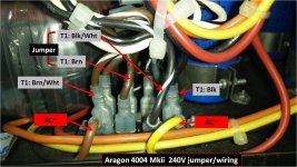
The voltage selector if you look at it closely has a jumper from 10-9 which in turn connects to the bottom leg of all the 4 primaries two black and two black/white. Then the jumper from 6 to 8 joins two separate winding's Brown just for 120VAC.
Thanks for examining the schematic.
I agree with your observation, however, my question was that shouldn't the other 4 primaries be connected as well?
As per the schematic, only two (browns) are connected. They should also be connected to the two brown/whites for 120v operation. That can only happen with jumper connecting 6 and 8 with 7 as well. Without that only 1 set of primaries will be used.
Rgds
Mayank
No only two of the primaries are for 120 VAC the other two are not used as they are for the 220 and 230 VAC. Yes typically all the primaries would be paralleled but in this case they are using two separate primaries sign of good quality!
Great insight!
I did not consider the possibility of there being separate primary winding's for 220/230V.
Hmmm. Could I request you to take another look at the schematic? In the 220/230V mode the two primaries are put in series. Why should they do that if the primaries are separate for the different voltages?
Perhaps I need to disconnect the toroids and take measurements with different combinations knowing the secondaries need to be at 70V/1.414 = 49.5V
Rgds
Mayank
Yes had another look and the 220 VAC is made with two primaries in parallel connected 10 to 9 then to 8 which joins Black /White of both primaries then the live is connected 6 to 7 which goes to the other ends of both primaries White/Black.
Then look at 230VAC it connects the same for the 9 to 8 and then 6 to 7 to the top of both primaries. So as you can see they have separate windings for 120VAC and separate tapped for 220VAC and 230VAC.
The wiring diagram is perfect and no mistakes just follow the jumpers and all should be well.
So for 120VAC all you need to do is make jumpers 10 to 9 and then 8 to 6 simple.
Good luck.
Dear formantjim:
Your insight was absolutely correct [bowing to the master!]
To close the loop on this I'm putting my notes here - in case someone else wants to rewire their Aragon 4004II for different input voltages.
1. The Aragon 4004II is a dual mono-block amplifier. It has two seperate toroidal transformers - one for each channel. Each of the toroids has two sets of primary windings. These primary windings are for different voltages of 210V/230V and 120V.
2. The schematic lists one primary pair as Black & Brown and the other as Black/White & Brown/White. The actual colors in my unit were Violet & Brown and Blue & White.
3. Setting the input voltage at 30.7V from my variac, with the Violet & Brown pairs I got 13.46V on the secondaries. With the Blue & White pairs I got 16.14V on the secondaries (obviously the primaries cannot be paralleled!).
4. This means connecting the Violet & Brown pair on 120V, I would get 74.4V AC - rectified to about 71V DC - the correct rail voltage. If the Blue & White were to be connected to 120V, I would get 89V AC - much higher rail voltage.
I am now in the process of recapping the unit and replacing the 4 massive 19,000uF/80V power capacitors as well. Will also reset the Bias and DC offset.
Rgds
Mayank
PS Oh yes, the amplifier is now working at home in the US (120V)
Last edited:
Use a Mains Bulb Tester (MBT) until you have proved there are no errors in your wiring.
A dual primary transformer is usually a "universal transformer".
It will have two separate 110/120Vac primary windings. Often these are specified as dual 115Vac.
You use these two windings in series for 220/240Vac supplies.
You use these two windings in parallel for 110/120Vac supplies.
In both of those alternatives it is possible to wire up the transformer incorrectly. This error will seriously damage your transformer. That is why I recommend the MBT. ALWAYS !!!!
Do you understand parallel and series?
Good reminder for everyone.
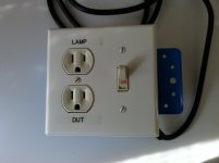
Several years ago I had made (see picture) a Dim Bulb Tester (DBT)/Mains Bulb Tester (MBT) which has been a permanent fixture on my workbench ever since. Noobs should heed Andrew's warning before powering ANY vintage or unknown audio equipment!
That was EXACTLY my initial thought process - that as the ARAGON 4004II had dual primaries, I needed to parallel the two winding's for 120V.
However, Mondial did NOT use "universal transformers"for their ARAGON amplifiers. As pointed out by formantjim, and noted from the schematic (post#1 above), only ONE pair of primaries (black/brown) are used for 120V. One CANNOT parallel the two primaries in this case without seriously damaging the transformer & amplifier. However, the primaries are to be connected in series for 220/240V.
I verified this by using a variac to measure the secondary voltages for each of the set of the primaries (post #7 above).
Not sure I understand why this question is being asked 🙄
Rgds
Mayank
Use a Mains Bulb Tester (MBT) until you have proved there are no errors in your wiring.
Several years ago I had made (see picture) a Dim Bulb Tester (DBT)/Mains Bulb Tester (MBT) which has been a permanent fixture on my workbench ever since. Noobs should heed Andrew's warning before powering ANY vintage or unknown audio equipment!
A dual primary transformer is usually a "universal transformer".
It will have two separate 110/120Vac primary winding's. Often these are specified as dual 115Vac.
You use these two windings in series for 220/240Vac supplies.
You use these two windings in parallel for 110/120Vac supplies.
That was EXACTLY my initial thought process - that as the ARAGON 4004II had dual primaries, I needed to parallel the two winding's for 120V.
However, Mondial did NOT use "universal transformers"for their ARAGON amplifiers. As pointed out by formantjim, and noted from the schematic (post#1 above), only ONE pair of primaries (black/brown) are used for 120V. One CANNOT parallel the two primaries in this case without seriously damaging the transformer & amplifier. However, the primaries are to be connected in series for 220/240V.
I verified this by using a variac to measure the secondary voltages for each of the set of the primaries (post #7 above).
Do you understand parallel and series?
Not sure I understand why this question is being asked 🙄
Rgds
Mayank
Attachments
Something else you might want to consider doing to this vintage amp. A few years back I remember someone pointing out that the 10ohm/5W resistors that are used for mains earth isolation (the ground board) on the secondaries are weak and would burn up and open rather quickly if a failure were to develop. It was suggested then that NTC thermistors be used in their places, CL-60's are around 10 ohms when cold and will handle way more current than those 5W resistors if a failure occurs.
FYI, The later 8XXX series Aragon amps used an anti-parallel pair of diodes paralleled with a 10 ohm resistor in this location.
FYI, The later 8XXX series Aragon amps used an anti-parallel pair of diodes paralleled with a 10 ohm resistor in this location.
I think you have misunderstood Form's post.......................
However, Mondial did NOT use "universal transformers"for their ARAGON amplifiers. As pointed out by formantjim, and noted from the schematic (post#1 above), only ONE pair of primaries (black/brown) are used for 120V. One CANNOT parallel the two primaries in this case without seriously damaging the transformer & amplifier. However, the primaries are to be connected in series for 220/240V.
I verified this by using a variac to measure the secondary voltages for each of the set of the primaries (post #7 above)..................
From what I understand of his long description, he is confirming that paralleled primaries are intended for 110/120Vac operation.
Or look at it this way:
Two primaries with T1 and T2 turns in them. Add them in series and the transformer primary has T1+T2 turns.
The primary will pass an operating current (A) and that generates an Ampere Turns (Amperes times Turns generates flux) parameter that suits 220/240Vac supplies.
Now throw away one primary and use the other with T1 turns.
For the same current the Ampere Turns will be A * T1. This will be roughly half the series parameter value. i.e. it works as a 110/120Vac winding.
BUT !!!!! the VA of the transformer is halved ! Because the amperes has stayed the same and the voltage has been halved.
Bring back the "thrown away" primary.
A1 passing through T1 and in parallel A2 passing through T2.
The total Ampere Turns is now A1*T1 plus A2*T2. This parameter is virtually the same as the the series ampere Turns parameter. (it was A*{T1+T2)).
It is identical if A1=A2.
The VA of the transformer remains the same whether the primaries are in parallel or series because the Ampere Turns is the same for the two alternative supply voltages. Importantly the dual primaries pass the same current in both the series and the parallel arrangements.
BUT!!! a Mains Bulb Tester must be used to prevent you damaging the transformer while you "find" the correct terminal interconnections.
In both the series arrangement and the parallel arrangement, the dual primaries can be wired "in-phase" or "out of phase". Out of phase connecting will result in enormous primary current and can very quickly damage a perfectly good transformer. The MBT prevents this potential damage.
Last edited:
Thank you Mayank for the schematic diagram...
while trying to rewire the power supply of my Aragon 4004II from 120v to 240v, I found out that the BRN and BRN/WHT is connected (by jumper) as same as BLK and BLK/WHT... which means both winding for each transformer being use for 120v mode.
http://www.diyaudio.com/forums/attachment.php?attachmentid=514847&stc=1&d=1447661669
and base from the schematic, for 240v wiring the connection should be
transformer T1:
AC~----BRN/WHT---000---BRN--BLK/WHT---000---BLK----AC~
could someone please correct me if this is wrong.
thanks
azirul
Attachments

Use a Mains Bulb Tester and when it is powered up either the filament will light up or not.
If it does not light up you can proceed to measuring voltages to confirm that everything is correct.
If it does not light up you can proceed to measuring voltages to confirm that everything is correct.
Rewire from 240v to 220v
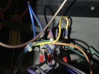
I just bought a used 240v and try to rewire to 220v, but the diagram and the color of the wires are all different. We just tried out by guessing, and almost kill the Amp.
The wiring looks the same but there are 2 different colors and got really confused.
I believe all experts in the forum can help me to figure out which jumper has to go.
Mine is like this
Attachments
If you use a Mains Bulb Tester it is almost impossible to kill the amplifier with a transformer wiring error.
Thanks for the information, i just wondering whether there is someone has done this, the colors are different. Using the bulb test, there is no risk of anything? Sorry to ask silly question, still a newbie, need heavy guidance. 😀
I don't know what mains voltage you have.
But here's an example for 240Vac.
A 40W bulb will pass 166.7mAac when fully hot. The hot resistance will be 1440r
If the voltage drops a bit, then the filament will be not quite so hot and the resistance will drop. Let's assume that @ 230Vac the current is 172mAac giving a resistance of 1333r
The mains AFTER the bulb is effectively 230Vac with a source impedance of 1333ohms.
The mains transformer is now fed from 10Vac instead of 240Vac. The total input power will be very approximately 10Vac * 0.172Aac = 1.7W
That cannot damage the transformer no matter how badly you mis-wire it.
That has to pass through the rectifier and charge up the smoothing capacitors to ~ 10/240* secondary voltage * sqrt(2) minus the diode drop, or ~ 0.8Vdc from a 25Vac secondary. That cannot damage a power amp if you have fitted the reverse protection diodes across the local decoupling capacitors.
That is what happens when the bulb turns on bright.
It prevents you damaging your transformer and your amplifier no matter how badly to wire it up.
Build a Mains Bulb Tester and use it.
Last edited:
@AndrewT: Thank you so much for all the detail information. I will do some shopping to make 1 bulb test equipment, which shown in your thread. I will try to do that in this weekend. At present, the amp is working fine but maybe it is not showing its potential. My house current voltage is between 215 - 222v /49.5 - 50.1 Hz.
- Status
- Not open for further replies.
- Home
- Amplifiers
- Power Supplies
- Aragon 4004II - rewiring from 240V to 120V