Happy to concede the 27 per minute, 0.3% swings are at least in part an eccentricity.
Looks to me like, that which appears to be amplitude modulation at a sub-harmonic of about 4-1/2 per minute, may be a measurement/sampling artifact. There's a very strong positive correlation between the amplitude minima, and the four instances per frame where 3 dots are needed to represent one full cycle of the higher frequency.
It'll take somebody smarter than me to sort that, though.😉
Cheers
edit: Forgot: My mistake earlier - the correct word is 'spurious', not 'specious'.😱
Last edited:
Rick PA Stadel, yes, I am convinced after much reading, that the 27 per minute oscillations are a function of record eccentricities. I did not put it in the table, but for the T/Ts listed the major oscillations were 33, 33, 36, 32, and 28, reading left to right. I was hoping that a math wizard was following this thread, and could shed some light on the sampling aspects of these observations.
BTW, correcting an error in the first post to this thread, the model designation for this T/T is not XE, but “AR The Turntable.” It says so right on the cover of the instillation manual!
Cheers
BTW, correcting an error in the first post to this thread, the model designation for this T/T is not XE, but “AR The Turntable.” It says so right on the cover of the instillation manual!
Cheers
It would be interesting to see a spectrum of the speed data - you might need to collect a longer sample of speed data to get good resolution though.
Mark Tillotson, I had already collected the data, but it did not seem to contribute any useful information about the variability in speed, or equally likely, my understanding of FFT analysis is just too shallow to draw any conclusions. So, the first attachment is a wide bandwidth spectrum of both the left and right channels. The second attachment is a narrow bandwidth spectrum of only the left channel. The right channel looks identical. These data were collected using a QuantAsylum QA401 Audio Analyzer. The RIAA preamp was a Sutherland KC VIBE.
I would appreciate anyone’s analysis of this data.
Cheers
I would appreciate anyone’s analysis of this data.
Cheers
Attachments
Sorry -- I think it might be above my pay grade.
Darned interesting, though. Thanks for posting.
I'll keep studying it.
Regards
Darned interesting, though. Thanks for posting.
I'll keep studying it.
Regards
Rick PA Stadel, no need to be sorry, we all get to that “above my pay grade” place sooner or later.
Cheers
Cheers
For those that have been following this thread, I would like to call your attention to another thread on these forums Turntable speed stabilty
I discovered it a few days ago. It is quite long at over 1100 posts and contains a lot of very interesting information. In particular, there is a discussion about a way to measure T/T speed using a polar plot technique.
Cheers,
ceulrich
I discovered it a few days ago. It is quite long at over 1100 posts and contains a lot of very interesting information. In particular, there is a discussion about a way to measure T/T speed using a polar plot technique.
Cheers,
ceulrich
A few final thoughts for this thread.
When I took the machine out of storage and cleaned it up, I refreshed the bearing oil with what I have used since I did the Merrill mods a few decades ago, i.e., the black Merrill bearing oil, I still had some left over. In the process of this refurbishment, I re-read the Instillation Manual for the AR turntable, where it calls for using “Number 10 machine oil” for the main T/T bearing. Over a number of days, I searched the Internet for a description or specification for No. 10 machine oil, and the best I could come up with was “light machine oil”, or “sewing machine oil.” So, I settled on using Singer sewing machine oil. I could have used one of the bearing oils sold for T/T use, but again, no specifications are given, so I had no idea how they compare to No. 10 machine oil.
I thoroughly cleaned the spindle and bearing well of old oil. Then I used just six drops of Singer oil in the well and a drop on the spindle. I ran the T/T for about 2 hours to let it settle in, and checked the speed. The variation in speed did not seem to be any different from when using the Merrill oil.
It is very difficult just looking at the speed variation to make a judgment if one pattern is better or worse than any other. I found some reviews of T/Ts where the speed deviations were as erratic as my old AR exhibited. Some were very inexpensive while others were considered high-end and were very expensive. As one reviewer (Micheal Fremer) said, “The speed-stability graph isn’t exactly pretty, but, as is often the case with such measurements, the turntable sounded far better than the graph indicated.”
Cheers,
ceulrich
your tests
Thanks for the test results Ceulrich
I am resurrecting my Ar The Table from storage also. The platter shaft measures .375" with the bearing well accepting a .377" machinist guage pin to the bottom and a .378" pin about .400" into the top before becoming tight. Seems a little loose to me.
Was planning on testing both light and heavy oils and light and heavy grease to see (or hear) any differece with that much clearance.
thanks again
dennis h
Dennis h, interesting information. I do not have the tools necessary to make any comparison measurements on my table. Do you think the bearing well was designed with that taper? I would be interested to learn of your results, particularly with grease.
As an after thought: Over the past few weeks I have made dozens of measurements as I tweeked, and they all looked different from one another, and all looked terrible. Out of curiosity, I calculated the standard deviation (SD) of the 60 values available for each measurement. The SDs ranged from 1.96 to 2.69. So, the speed variation is only on the order of 2-3Hz.
Cheers,
ceulrich
Dennis h, interesting information. I do not have the tools necessary to make any comparison measurements on my table. Do you think the bearing well was designed with that taper? I would be interested to learn of your results, particularly with grease.
Cheers,
ceulrich
Uh, no
This turntable sat in the trunk of someones car for a while without the shipping bolt engaged which is why I was worried about the platter bearing and the bearings in the RB250 tonearm.
If one bought a Merrill polymer subchasis from vinylnirvana.com it would come with .002 clearence which (without his experience) I think is loose.
a ways off from tests,
dennis h
I got interested in this having tried the program mentioned at the start of the thread using a tone from a test record. I thought it would be an interesting thing for my first Arduino project.
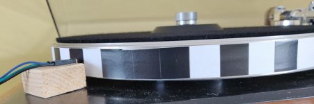
It turned into a series of false starts trying different sensor types. Eventually I settled on an analogue IR reflectance sensor that worked in the way I wanted and made a strip of alternating black and white bands that I pulled tight around the platter rim. It stays there without glue on the platter.
I'd tried just printing the strips, but found that normal printer paper didn't get a black that was sufficiently black enough for the sensor to reliably discriminate with the white paper. I printed guides on the paper and used electrical tape of 18mm width 🙂. I will try using photo paper for the strips as the blacks on those are solid and I can reduce the strip to the 10mm I'd originally planned.
Initial results are that my Heybrook TT2 is running slightly slow @ 32.78rpm, but the speed is incredibly stable with virtually no wow except for a weird 0.5% blip every couple of minutes. Mains I suspect. Still working on producing reliable flutter measurements, but it looks like they're a close match to those from the test program.
This has been an interesting project, learned lots. The development on Arduino eventually turned out to be good fun, but I tried five different development environments before I found something that wasn't either so primitive I thought I was back in the early 90's or so complex they looked like they'd been deliberately obfuscated.
Eventually I settled on VsCode and PlatformIO, though CLion and PlatformIO looks interesting and I'm very familiar with Intellij products.
I'll report back when I've sorted out the problems with flutter calculations. I'll probably add a display too because I'll need that for the preamp I'm planning to build.
Last edited:
StevenCrook, very interesting, I was unaware of the Arduino products, a quick check of the website peaked my interest, I will have to go back and investigate more. Back to TTs, the strobe approach does eliminate the off-center record problem. Can you post a bit more information; for example, are you counting revolutions or are you measuring time some how and calculating RPM, also it would be interesting to know the strobe pattern, i.e., the black and white spacing. I suspect that will define the precision of your measurements.
Cheers,
ceulrich
Cheers,
ceulrich
I wanted a method that eliminated the need for a disc and the errors that inevitably introduces, but I have to confess that my main aim was getting experience with Arduino, not producing cast iron results. But you know, mission creep. I got interested in what I could squeeze out of the program I was writing and whether I could produce a small, self contained, battery powered unit. Something I could plonk alongside any platter with a suitable strip attached to it and get a summary on a screen and export data for a spreadsheet if I felt truly anal about it. Useful skills to learn.
On the Arduino, the sensor is read from an analog pin and returns 0 for completely reflective and 1023 for completely absorbent. I get values of roughly 70-80 for white paper and > 800 for the black tape I've used. There's a world of difference between the two, and they make good plateaus in the figures returned as the turntable rotates and, while completely over one or other strip, there's no significant variation. The transition between high/low reflectance is relatively swift, and most important, decently consistent.
I decided that the sizes of the strips didn't matter as long as they were consistent, and wide enough for the sensor to return a series of very similar readings. As I mentioned at the head of the thread, I'd originally thought 10mm, but 18mm tape was convenient and seems satisfactory too. Essentially I need a square wave with slopes up and down from the plateaus.
I terms of errors, I think the main one is going to be calculating flutter. Inevitability there's going to be small variation in the size of the tape either in the tape itself, or it not being entirely vertical on the TT or from being stretched slightly when it was stuck to the paper. These are (for me) going to remain known unknowns. To minimize them I printed guides (LibreDraw) for sticking the tape and for cutting the strips from the paper. It worked pretty well IMO.
As mentioned at the head of the thread, I'll try photo paper and the deeper blacks it gives, but they weren't dark enough on standard printer paper. I don't have a laser printer any more.
I had to use A4 paper, one sheet gave me enough strips for two runs around a TT or spares for an inevitable dumb mistake. My method is to cut the strips (steel ruler and scalpel) using the guides, then for each strip cut one end back to a white edge, and join the strips using double sided tape over another white edge. One advantage of the black electrical tape is that I can butt the white part up against it when joining them.
The longer black strip was a useful accident. I didn't fancy my chances of choosing strip sizes that finished exactly around the TT, that's for manufacturers with more kit than I have. I'd originally planned to code around it then thought about it a bit more, and turned it to my advantage.
For RPM I rely on timing the reappearance/disappearance of the longer black strip and wow comes from variance in the time of disappearance of that strip.
The smaller strips are of even size and I'm using those to give me figures for flutter. At the moment I'm collecting the sum of all the times taken for a strip to pass the sensor, I also collect the sum of the delta between the current strip time and the averaged strip time.
When I report, I use the average of the sum of the deltas (yes, I know) for strips divided by the average of strip times to give a percentage. So far at least this passes the plausibility test, but I'm not entirely convinced I have this right. I'm a programmer and profess little math skill and what I have is acquired on a need to know basis.
I'm pretty sure I can count the number of smaller strips and keep figures for each strip. This'll eliminate variations caused by micro differences in size of the strips, but how that's presented on a screen I really have no clue. Yet. I'll do some reading around and thinking.
At the moment I'm trying to make the program adaptive so I don't have to use constants to determine when reflectance values indicate a strip starts/ends. The program waits for the TT to start and for rotation to stabilize. Once stable the square wave will be analyzed to determine the reflectance values for the plateaus. This way, I can make new, different strips and not have to furtle with the code.
I'm working on this auto-configuration at the moment, then back to polishing the numbers, considering a display, and data export.
Excuse the dust on the TT. Had the lid off for a few days while I've been fiddling with this. It'll need a good going over before I play anything...
StevenCrook, OK, the pictures help a lot.
For RPM, you are measuring the time the longer black strip is detected, and then calculating the RPM from that time, is that correct? How long is the longer black strip, it looks to be a bit longer that 3 widths of tape? How is time being measured?
For RPM, you are measuring the time the longer black strip is detected, and then calculating the RPM from that time, is that correct? How long is the longer black strip, it looks to be a bit longer that 3 widths of tape? How is time being measured?
Yes. Just timing the trailing edge of the long strip on each rotation and I can work out it's that edge because it's at the end of the longest strip and wow is the variation in that time as a percentage of the last time.
The rules for the band around the platter are:
Everything else is worked out by software 'in flight' with some basic measurements taken during the first two or three rotations of the platter.
I've not made up my mind how to present flutter, but I'll have lots of data. And you can't have too much data.
It's been a few years since I had to write any c/c++ and it's taken a week or so for it to not be an effort. But I still prefer Java and C#. Been fun so far and nice to see I still remember it.
The rules for the band around the platter are:
- Strips must be different enough in reflectance that they can be distinguished
- Strips must be long enough to give a good plateaux in the signal
- One strip must be detectably longer than the others
- Strips must have sharp edges to give the best possible transition between them.
Everything else is worked out by software 'in flight' with some basic measurements taken during the first two or three rotations of the platter.
I've not made up my mind how to present flutter, but I'll have lots of data. And you can't have too much data.
It's been a few years since I had to write any c/c++ and it's taken a week or so for it to not be an effort. But I still prefer Java and C#. Been fun so far and nice to see I still remember it.
Hi StevenCrook,
Glad to hear the rust fell off your C/C++ quickly. Sounds like you're on an interesting path.
Just have a quick tip and a thought that come out of working with thermal printers a while back.
We were trying to register images on polyimide labels coming out of the printer at almost 3 per second, using an infrared transmission setup to locate the labels. Your situation won't have at least two of the problems we had. But you can still sharpen the edges if you want to, using one or two small lenses -- something like an inexpensive microscope objective lens element.
The second big problem came from digitizing the output of an optical system. At the time microcontrollers with onboard A/D were relatively new and seemed like a certain design shoe-in. But a comparator/counter arrangement can be more consistently accurate at locating the event in time.
You could be completely arbitrary with your black tape placement, then only measure the width of the tape - the dark time. If your outer rim diameter is 254mm, and I haven't buggered the arithmetic, each 19mm band of dark should measure about 42.859 milliseconds. If you wire a comparator to hold off a synchronous prescaler by its reset, then let the microcontroller count MSB's or MSB-transitions, it will avoid the units-flicker (there's a better term for it - can't remember) that is such a nuisance.
Then you could have as many speed measurements (per revolution) as you're willing to stick black tape strips around the rim -- and the spacing is arbitrary.
Cheers
Last edited:
Thanks for a really helpful response, your calcs make sense 🙂
I tried a number of different sensors and the current IR gives a pretty good response, though there's a bit of fall time on the transitions from the white sections, but the peaks/troughs are still well enough defined AFAIKT.
I been worried about the width of the sensors causing a much wider distribution of values and would have tried a laser spot+photo sensor if I'd been able to find one that looked plausible.
I'm using an Adafruit Feather M0, so SAMD21 chip, decent ADC and high clock speed. But I chose it mainly because I can plug in and charge a LiPo directly, so can run it from battery without extra boards. I have a couple of other potential projects that'd require a battery, including one where I'll need to charge the battery from a heat source.
I run a calibration that includes making 40k measurements @ 100us intervals and collecting counts into buckets (1024, 1 for each potential sensor reading) for sensor readings. Then go through the buckets from each end looking for a peak in the counts, go ten buckets on checking for declining values, then backtrack until I find a count that's >= 25% of the maximum. I get max white, and min for black. Which, AFAIKT is all I need.
I've got to rework my measurement code and get new numbers based on the bucket/edge approach.
On the C/C++ front, a lot has changed in the decade (or so) since my last serious use of it. Who thought I could use STL in programming a microprocessor! Code generation looks to be much better too. I remember when templates, and STL in particular, could cause terrible code bloat, initial impressions are that's not an issue any more. Dev environments++ too. Much closer to JetBrains Idea, but still not quite there.
Almost civilised!!!
I tried a number of different sensors and the current IR gives a pretty good response, though there's a bit of fall time on the transitions from the white sections, but the peaks/troughs are still well enough defined AFAIKT.
I been worried about the width of the sensors causing a much wider distribution of values and would have tried a laser spot+photo sensor if I'd been able to find one that looked plausible.
I'm using an Adafruit Feather M0, so SAMD21 chip, decent ADC and high clock speed. But I chose it mainly because I can plug in and charge a LiPo directly, so can run it from battery without extra boards. I have a couple of other potential projects that'd require a battery, including one where I'll need to charge the battery from a heat source.
I run a calibration that includes making 40k measurements @ 100us intervals and collecting counts into buckets (1024, 1 for each potential sensor reading) for sensor readings. Then go through the buckets from each end looking for a peak in the counts, go ten buckets on checking for declining values, then backtrack until I find a count that's >= 25% of the maximum. I get max white, and min for black. Which, AFAIKT is all I need.
Code:
At the WHITE end. Sensor reading top, count of reads bottom
    123    124    125    126    127    128    129    130    131    132    133    134
      8    295   1073   2563   5108   4857   2225    769    445    326    248    196

At the BLACK end
    947    948    956    982    997   1006   1012   1015   1021   1023
     11     12     11     12     13     11     11     12     13  17114
I've got to rework my measurement code and get new numbers based on the bucket/edge approach.
On the C/C++ front, a lot has changed in the decade (or so) since my last serious use of it. Who thought I could use STL in programming a microprocessor! Code generation looks to be much better too. I remember when templates, and STL in particular, could cause terrible code bloat, initial impressions are that's not an issue any more. Dev environments++ too. Much closer to JetBrains Idea, but still not quite there.
Almost civilised!!!
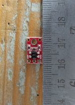
Got back to this after a longish hiatus and I've changed the IR sensor and I'm using a different board. I'm using to a Pololu QTR-HD-02A because I was getting inconsistent performance with the original single sensor version. The new board has two sensors with lenses and I have control over the level of illumination provided by the IR lamps.
Also I wanted to experiment with connecting it to a network and thus to my phone, so I got a Feather M0 WiFi.
This time round I'm averaging the readings between the two sensors. There are other boards with more sensors, I may try using a block of 4 sensors (stacked vertically) and then have them 'vote' on what's underneath them taking the majority verdict. Just out of curiosity.
But so far things look pretty good with what I have. I can start the thing running and then turn on the TT, s/w waits for the rotation to stabilise, counts the bands and coughs out the RPM etc on every turn.
I have to verify the results somehow, but it looks pretty solid to me ATM.
So on to recording and displaying bucket times for each individual stripe around the rim of the TT and getting the information off the board.
It's what I did. I only went with precise placement and even band widths because I thought I might need it and it was convenient to use black tape. But, as it stands I can detect the edges of bands pretty distinctly and as long as there's a significant difference in length (at least 2x) of one band and any of the others everything just auto configures.
Also I wanted to experiment with connecting it to a network and thus to my phone, so I got a Feather M0 WiFi.
This time round I'm averaging the readings between the two sensors. There are other boards with more sensors, I may try using a block of 4 sensors (stacked vertically) and then have them 'vote' on what's underneath them taking the majority verdict. Just out of curiosity.
But so far things look pretty good with what I have. I can start the thing running and then turn on the TT, s/w waits for the rotation to stabilise, counts the bands and coughs out the RPM etc on every turn.
Waiting for rotation to start
Determining reflectance bands - 40k samples, at 28-34us per call, average: 28us
Determined reflectance bands: lower: 77, upper: 747
Checked rotation is stable
Waiting for SyncBand: Max Band: 33.551, Band: 33.934, Band count: 1
Found Sync Band: Got To Sync, Max Band: 33.934, Sync Band: 117.553, Band count: 2
Counting bands: 25
Counted bands: 25, Sync Band: 117.553ms
Rpm: 32.735, Wow: 0.0000%, bandTime: 117ms, rpmTime: 1832.884ms, Revs: 1045
I have to verify the results somehow, but it looks pretty solid to me ATM.
So on to recording and displaying bucket times for each individual stripe around the rim of the TT and getting the information off the board.
You could be completely arbitrary with your black tape placement, then only measure the width of the tape - the dark time.
It's what I did. I only went with precise placement and even band widths because I thought I might need it and it was convenient to use black tape. But, as it stands I can detect the edges of bands pretty distinctly and as long as there's a significant difference in length (at least 2x) of one band and any of the others everything just auto configures.
- Home
- Source & Line
- Analogue Source
- AR Turntable Question