I had a quick play with the Apt topology in a sim.. I believe ostripper did too. AS you say there are lots of lovely devices now (Fairchild have a good set) that make triples very well.
Jed mentioned that...I had a quick play with the Apt topology in a sim.. I believe ostripper did too. AS you say there are lots of lovely devices now (Fairchild have a good set) that make triples very well.
Im wondering if they would drop in in place of the original devices ?
bob
the transistors i'm thinking of are too big to fit in place of the TO-3 devices, as they're TO-247 and don't have the angled corners TO-3P devices do. those would be the MJl0281 and MJL1302
Last edited:
Jed
Got a question for you. On the 2SC1345's is there an hfe range i should be looking for ?
Or the same for the other small signal transistors ?
Bob
Got a question for you. On the 2SC1345's is there an hfe range i should be looking for ?
Or the same for the other small signal transistors ?
Bob
the transistors i'm thinking of are too big to fit in place of the TO-3 devices, as they're TO-247 and don't have the angled corners TO-3P devices do. those would be the MJl0281 and MJL1302
The smaller ON's (NJW) 0281/0302 do have the "corners" (TO-3P). At only $1.20 apiece , you can't go wrong. 🙂 VERY durable devices (6mm dies).
OS
now i'm drooling......
TO-3P devices with the corners will usually fit in the same place TO-3 metal devices did. you have to run a wire to the collector lead, either through the unused mounting hole, or to a round lug that goes in under the head of the mounting screw you do use (which still allows you to remove the device without unsoldering anything). the B-E leads may not fit in all sockets, as they aren't round. the APT-1 sockets were made for round pins, so it may be difficult to get TO-3P devices to seat in the sockets.
TO-3P devices with the corners will usually fit in the same place TO-3 metal devices did. you have to run a wire to the collector lead, either through the unused mounting hole, or to a round lug that goes in under the head of the mounting screw you do use (which still allows you to remove the device without unsoldering anything). the B-E leads may not fit in all sockets, as they aren't round. the APT-1 sockets were made for round pins, so it may be difficult to get TO-3P devices to seat in the sockets.
Last edited:
Jed, A few board fotos of the APT 1 board.
Got a few photos up of one of the boards, can anyone tell me if these were a factory tweek or someones sloppy work. You cant imagine all the silicon goop on these boards. It looks to me that caps were snipped off and new just tacked to resistors or what ever the could.
Im going to clean the both boards up and replace the caps.
bob
Attachments
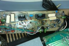
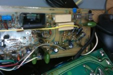
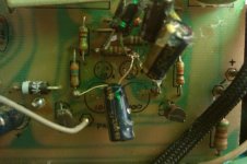

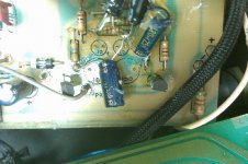
looks like somebody didn't want to properly disassemble the amp module to work on it. very sloppy work. at least it looks like the traces underneath are intact. if i had gotten this board at the factory, i would have rebuilt it. i would have literally stripped the board down bare, clean off all the goop and repopulate it. somebody was in an awful hurry. one of the things that was found out about leaving long leads on electrolytics was that it made the amp susceptible to RFI in the 25-30Mhz range. we had a company literally next door that grew silicon ingots for making transistors and diodes, and the 25Mhz radiation from their induction furnace was a real problem, but it allowed us to find out real quick how good a particular revision of board or assembly method would stand up in high RF environments.
btw looks like about a rev 4 or so. rev 2 and 3 had a lot of hookup wire jumpers that were color coded by length.
btw looks like about a rev 4 or so. rev 2 and 3 had a lot of hookup wire jumpers that were color coded by length.
Last edited:
looks like somebody didn't want to properly disassemble the amp module to work on it. very sloppy work. at least it looks like the traces underneath are intact. if i had gotten this board at the factory, i would have rebuilt it. i would have literally stripped the board down bare, clean off all the goop and repopulate it. somebody was in an awful hurry. one of the things that was found out about leaving long leads on electrolytics was that it made the amp susceptible to RFI in the 25-30Mhz range. we had a company literally next door that grew silicon ingots for making transistors and diodes, and the 25Mhz radiation from their induction furnace was a real problem, but it allowed us to find out real quick how good a particular revision of board or assembly method would stand up in high RF envireonments.
Jed
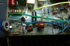
Im thinking about completley rebuiding the boards myself. After looking close up how sloppy the work was done. The more I look at this board, I know it has to be done. The traces look good but the slop and the amount of crud has to go. I have a question for ya, on this board whomever cut the 2 leads to the moxie, any idea what number it is ? Im figuring if I clean up this mess im gonna hoe to the end of the row.
Taking out the second board tommorow, but from the looks of it, it's the same.
bob
i don't remember the number, but i know it was one that was something like 50K up to 80C, then began to decrease rapidly in resistance to reduce the overall gain of the amp from 30 to something closer to 15 or 20, (which would reduce the amount of power out and allow the amp to cool off a bit). a but not so quickly that it was noticeable. think of it as a "soft" thermal protection.
Jedi don't remember the number, but i know it was one that was something like 50K up to 80C, then began to decrease rapidly in resistance to reduce the overall gain of the amp from 30 to something closer to 15 or 20, (which would reduce the amount of power out and allow the amp to cool off a bit). a but not so quickly that it was noticeable. think of it as a "soft" thermal protection.
Thanks, Ill pull out the moxie tonight and see what I can find out.
And check the revision numbers, I do know that the protect board it rev 7.
The one channel on this amp has been running with the moxie disconnected, I don't run the amp very hard. It runs cool, barley warms up after running all day.
bob
the moxie only really matters if you run the amp near clipping into a low impedance load. i remember however that a very small number of them had leakage to the case which caused oscillation (or sometimes the ground lead to the moxie would get pinched to the case causing oscillation from a ground loop). if it gets into the temp range of the moxie, you may notice a difference in levels between the channels because one moxie is disconnected and the other one isn't. i've used an APT-1 as a PA amp in a small venue driving some Peavey cabinets with no ill side effects from running the amp hot. but it also had very adequate ventilation, and a minute or so break between songs.. that amp did have the moxies installed, but if i were going to use one in a rack with forced air cooling i think i would remove them.
one of the things i'm thinking of for a modernized APT-1 is thermal sensored fans or audio driven fans (Pioneer and Panasonic use this technique very effectively, and Pioneer has a combination of thermal and audio powered fans, so that after running hot, the fan continues to operate until the temp gets to the point where the audio control of the fan takes over again). normally under 10 or 20 watts the fan is off. above this level, audio is tapped and rectified from the output stage (or fed into the gate of a FET controlling the fan) at this level the fan noise is inaudible anyway. as long as the thermal sensor threshold isn't reached, the fan speed is linearly controlled by the average audio level. once the thermal threshold is reached the thermal sensor turns the fan on full speed until the temp comes back down.
the convection cooling of an APT-1 is quite good to begin with, especially in later revisions that used a one-piece extruded heat sink. the sheet metal heat sinks were quite adequate, the extruded ones were better (they had more surface area, and no thermal interfaces between layered sheet metal like the original heat sinks). in the last months APT was making amps, layered sheet metal was used again, and some of the amps from that time had one of the fin layers bent in kind of an angled manner (half-octagon shape). these were the last of the rev 10 amps.
Guys
Im starting on the APT, I have the boards out and will be working on them soon.
Here is a link to my pbase photo site if you all would like to have a look.
If you look closely you will see differences in the attached components on the boards. They are marked revision 3. the boards are otherwise identical.
Apt 1 amplifier project Photo Gallery by bob at pbase.com
bob
Jed
Ever have a look at Central Semi CEN-U10 and CEN-U60 transistors for the pre drivers ? They are TO-220 cased equiv's to the motorola's used in the APT.
Aside from the case difference they are a drop in.
bob
Ever have a look at Central Semi CEN-U10 and CEN-U60 transistors for the pre drivers ? They are TO-220 cased equiv's to the motorola's used in the APT.
Aside from the case difference they are a drop in.
bob
B-C-E or E-B-C? the mot parts were getting hard to find even then back in 1985 because mot discontinued them. they were difficult to find replacements for with a Ccb of 3pf, Vceo of 300V, Ic of 500mA and Pc of 10W. it was a rather unique pair of devices.
are the cen parts in current production?
are the cen parts in current production?
The MPSU10/U60 was rated at 1W at 20°C.
Take a look at the MPSW92/W42 curves, same pin-out, 1W at 20°C, might be a bit faster.
Take a look at the MPSW92/W42 curves, same pin-out, 1W at 20°C, might be a bit faster.
B-C-E or E-B-C? the mot parts were getting hard to find even then back in 1985 because mot discontinued them. they were difficult to find replacements for with a Ccb of 3pf, Vceo of 300V, Ic of 500mA and Pc of 10W. it was a rather unique pair of devices.
are the cen parts in current production?
Central semi EBC and yes they are in current production
Attachments
the 10W figure comes from the data sheet, with the 1W listed also. i'm guessing the 1W figure is free air, and the 10W is heat sinked and the collector tab maintained at 25C. the 1W figure is sufficient, as the devices are run at something like 20mA or less.
Jedthe 10W figure comes from the data sheet, with the 1W listed also. i'm guessing the 1W figure is free air, and the 10W is heat sinked and the collector tab maintained at 25C. the 1W figure is sufficient, as the devices are run at something like 20mA or less.
Yes, and looking at the board a original and heat sinks, the Cen transistors fit perfectly.
If I were going to recreate the APT 1, Id seriously look at the Central semi's.
I have alot of work ahead of me on this one, taking your advice and rebuilding the boards.
With the APT, What is your recommendation for replacement resistors ?
I can go metal films, metal oxide or carbon.
Im also wondering, on the boards the values of caps, I noticed that most of the electrolytic's are uprated, 1uf going to 10, 47uf going to 100. Im thinking just follow the schematic.
The .33 @100v I can replace with a good film that fits, prolly Panasonic's or Wima.
Also for emitter resistors, I can reuse whats there, Or I have a bunch of .47 ohm, Dales that measure right at.47 @ 3 watts versus 5 watts for the originals. but the Dales are about 1/4 the size of the sand cast. Do you see a problem with using a lower wattage ?
For the diode's I see 1N4007 and looks like 1N4148's which I have a ton of, the zener's I can get locally.
bob
original resistors were metal or carbon film, except for the isolator (10 ohm 1W carbon comp) it later got switched to a metal film. keep the electrolytics the same as the schematic. the ones in the protection circuit and in the servo are time constants. the servo time constant is set for a 5hz rolloff, and the protection time constants are set to match the thermal time constant of the output devices. it's important that the values of these don't get monkeyed with. the others (C1, C27, C28) aren't critical.
1N4007's, 1N4148's and the zeners are all pretty common. the 4148 diodes are used where a fast transition is required, such as in the baker clamp.
1N4007's, 1N4148's and the zeners are all pretty common. the 4148 diodes are used where a fast transition is required, such as in the baker clamp.
- Home
- Amplifiers
- Solid State
- APT 1 power amp – undeservedly forgotten