I would like to know if anyone of us here,
as worked with accoustical knowledge, on engine tunning of intake to exhaust systems ??
I have read multiple books
( probably near 50 now ... )
On application of fluid mechanics and such to design and or tunning of engine components ,
and i have yet to see one that talks about the accoustical theory part of waves for tunning ...
they all state the obvious base that waves are created then propagated , and used for tunning ..but never do they go in the path of actually telling how to use,
how to predict and or how to tune for ..
What i am talking about here,
is using waves tunning with intake part, camshafts timing and lift, piston speed, valves, exhaust port to headers collectorts to exhaust end ....
If no one has any experience with that ,
i'd like to have help on finding how we can use the accoustical stuff to work with engines ..
i'll have to get reading my Master Handbook of Accoustics...but even there, i recall reading the basis,
but not real exemples on how waves acts and bouces and all ...
thanks for any help 🙂
Hi
Try a search like this one:
http://www.google.be/search?hl=en&a...r+engine+diagnostic+exhaust&btnG=Search&meta=
And then refine by examining the results
LV
Try a search like this one:
http://www.google.be/search?hl=en&a...r+engine+diagnostic+exhaust&btnG=Search&meta=
And then refine by examining the results
LV
Do an IP search for the international patent classification F02B27 described as:
"Using kinetic or wave energy of charge in induction systems, or of combustion residues in exhaust systems, for improving quantity of charge or for increasing removal of combustion residues"
Regards
Charles
Edit: Sorry the above is the European classification but this shouldn't pose any problem if you use a database where you can search after european classifications.
A good point. I was obsessively interested in this in the 1960's when I wanted to spend my life designing formula One grand Prix cars. By chance the first serious book I read was by L.K.J. Setright who continued the series begun by Laurence Pomeroy (and his, Pomeroy's, father, I think). "The Grand Prix Car" by Setright ends in 1966. But in that he details exactly what you are after. He goes into the resonances and pipe length etc. This material is around and has been pretty exhaustively (if you excuse the pun) dealt with when you find the right source.
The theory leads to variable length induction manifolds i.e Mecedes sport cars of the mid 50's and then again much more recently, variable valve timing etc etc.
The theory leads to variable length induction manifolds i.e Mecedes sport cars of the mid 50's and then again much more recently, variable valve timing etc etc.
The fact that many books don't go into the specifics of inlet/outlet manifold tuning is probably because there is not very much to it*, is simply a matter of reflected waves at an pipe ending/expansion chamber, the speed this wave travels is fairly constant, the speed of sound, therefore the timing at which the reflected low pressure wave (in case of exhaust system) arrives at the inlet valve is only determined by the pipe length. The timing is then determined from the fact that you want an low pressure wave at the exhaust valve exactly around the time it opens.
Off-course this tuned state can theoretically hold only for one value of the engine speed, in practice this means a rpm small range.
The last argument is also the reason why intake/exhaust tuning is not always used on normal cars, besides the fact that the intake/exhaust geometry and especially length is severely limited due to space constraints. Although the more performance oriented makes like BMW, Audi etc are starting to use variable inlet geometry, but this adds just another complex part to the engine bay.
BTW, it is needless to say that in applications were engine speed is fairly constant intake/exhaust tuning is extensivly applied, like prop airplanes.
Hope to cleared some things up,
I study Automotive engineering as a master track so if you have any more questions you're welcome...
*I only talk about simple pipe length tuning, off-course there are other more complex methods, like adding Helmholtz resonators and the like.
A friend of mine had a 4 cylinder engine with 4 into one tuned exhaust, at a certain distance down the pipe in the collector there was a flat plate welded into the pipe partially obstructing it. the obstruction did provide some restriction and turbulence but the idea of it was the exhaust valve opened, the pressure pulse (bang) travelled through the hot gas in the pipe, about half of the compression wave reflected off the washer, back up the pipes and off the back of the exhaust valves, hopefully just before the valve opened. The exhaust valve was supposed to open into a rarefraction right after the pulsation to help extract exhaust gas.
No idea if it worked as intended.
Apparently it was incredibly loud with these pulsations reinforcing each other. I think it would only work for a very limited rev range.
I have also heard of using temperature sensitive paint on the exhaust during a dyno run to determine the optimum length of pipe after the collector in a set of extractors. You trim it off at a hot or cold spot, not sure which. This also make an incredibly loud system.
Neither of these methods are suitable for street vehicles, these are open exhausts with no muffler.
have a look at 2 stroke racing bikes, they have a rather interesting looking expansion chamber on them
Australian made 4 litre 6 cylinder ford engines use a variable length intake manifold. with a set of butterflies in the inlet runners to change the length. I'm sure other engines use this method also.
remember with the exhaust gas temperature and composition is not air, the speed of sound will be different.
Dont forget to spend $13000 on a new battery wire, it will make your car feel more open and dynamic, and the slow speeds will be darker 😀
I never thought about until now, but the air horns on the Webber carb in my ’69 Mini look just like the flaired port in my subwoofer.
I imagine there’s a lot that can be done with aftermarket parts to improve performance and tuning using acoustical modeling. However, there’s a ton of variables under the hood of a car that one doesn’t have to deal with in a listening environment. I also imagine the car manufacturers perform extensive tests and tuning to optimize performance and economy. Unlike what the conspiracy nuts will tell you, I highly doubt that there are substantial gains to be had that will not result in deficits somewhere else. Huge exhaust = noise, popping, and size limitations. Huge intake = noise, worse idle, lean running, etc. Exotic cams and variable-valve-timing = cost, complexity, poor idle, etc. With naturally aspirated engines, I think there are a lot of improvements in head design left to be done to improve volumetric efficiency. I saw an article on a cylinder head that used some sort of rotary ball-valves that greatly reduced friction, improved valve actuation speed, and improved the directionality of airflow into/out of the combustion chamber. The head was also thin and light. I haven’t seen anything about it in a long time, so it either doesn’t work, or there were issues with sealing the valves, or Detroit killed the inventor – who knows. . .
I imagine there’s a lot that can be done with aftermarket parts to improve performance and tuning using acoustical modeling. However, there’s a ton of variables under the hood of a car that one doesn’t have to deal with in a listening environment. I also imagine the car manufacturers perform extensive tests and tuning to optimize performance and economy. Unlike what the conspiracy nuts will tell you, I highly doubt that there are substantial gains to be had that will not result in deficits somewhere else. Huge exhaust = noise, popping, and size limitations. Huge intake = noise, worse idle, lean running, etc. Exotic cams and variable-valve-timing = cost, complexity, poor idle, etc. With naturally aspirated engines, I think there are a lot of improvements in head design left to be done to improve volumetric efficiency. I saw an article on a cylinder head that used some sort of rotary ball-valves that greatly reduced friction, improved valve actuation speed, and improved the directionality of airflow into/out of the combustion chamber. The head was also thin and light. I haven’t seen anything about it in a long time, so it either doesn’t work, or there were issues with sealing the valves, or Detroit killed the inventor – who knows. . .
Talking about normal cars, cost is a very big factor, and normal car manufactures (to my knowledge) usually do not get trough the trouble of optimizing an entire manifold system to a detail which is simply VERY costly to produce in series due to added production costs .  Furthermore this argument is backed by the fact that interchangeability is important to, different engines are used in 2 or 3 types of one make. 😱
Furthermore this argument is backed by the fact that interchangeability is important to, different engines are used in 2 or 3 types of one make. 😱JinMTVT said:i'd like to have help on finding how we can use the accoustical stuff to work with engines ..
Nothing to do with tuning an engine but Ford did a neat thing a few years ago in their pick ups. They added a resonance chamber to the intake to make the engine sound more manly. No kidding, a chamber that does nothing more than make it sound good.
Woa ...i'd thought that most of you guys would quote something more advanced than 60's cars,
or FORD as good designs ..
where to start :
Cal Weldon: well ..honda has been doing that extensivly in both intake and exhaust to remove unwanted noise peaks from engine or combustion ...BMW and BENZ been doing that in intake for a few decades ..
Ford never invented anything ...point
check this nice "twin loop" exhaust muffler design from MUGEN company ( son of Mr. Soichiro Honda founded mugen as a "motorsports" division of HONDA )
http://www.honda-acura.net/forums/showthread.php?p=2211800
this muffler design is tunned to cancel a certain frequency and its surrounding..the exhaust gaz and waves passes twice inside the can where there is an exchange tunnel ( holes between the 2 )
i've had this muffler on one of my cars recently...
and i have to say that is sounds just perfect! 🙂
Speedsmile :
i have to say that you are wrong ...
most quality manufacturers
( again with honda,bmw as kings ) tune all the intake and exhausts very well on their car ..and i could even say some are extensivly tunned for a specific purpose..
let's take and intake manifold as an example
wich is usually in aluminum of 2 or most casts pieces
well it doesn't cost anythin more to cast a longer or shorter piped intake manifold, and designs of the manifold itself for tunning doesn't have to cost anything more ...usually surfaces of an intake manifold doesn't ahve to be perfectly smooth , and casting gives a good possibility for funnelling ...
exhaust manifolds in the type of seperated welded tubes cost more than cast rough iron manifold,
but changing the lenghth or diamter of it's pipes,
the 4-1 or 4-2-1 design, doesn't change much in the price of the item ...
Look at M cars from Bimmers and Type R cars from HONDA and you will see very good quality parts that were designed almost perfectly for their purposes...
DCPreamp :
First thing , i have an R&D company, in wich we will be developping a new type of combustion engine,
that i have "invented " trying to make this thing work correctly ( been designing it for a few years now )
but since this will take huge funds, and i do not want to put my primary buisness on its knee, we are currently
manufacturing racing car parts and selling those to pay for the developement costs of the engine ..
I am no amateur in designing custom parts for car,
and i ain't talking here about changing a muffler pipe for looks, or trying to achieve 10HP gains on a 100hp engine with a single intake tubbing change ..
we make all the parts we can with the limited equipement we have, and have custom parts made almots everyweek for engines and suspensions now..
Yes everything is a compromise in cars, just as in audio
but depending on the application, it can be very largly worked on...
an 2.0l L4 engine that produces 200hp and costs 5000$
will probably be designed to make 100K KM + on a street car ...
but one could probably do 325hp with the same engine
( near theoritical limits for an L4 ) and make it also last 100K KM ..but it would costs near 50 or 75 000$ in work
you can also make a 350hp engine that will only be good for a few 1/4 runs ..2-3
and will cost not that much compare to the 100K KM one
The theoritical limits of NA ( normally aspirated ) engines is the 110-120% volumic efficiency that can be attained
VS the $$$$$ put toward the following :
- friction
- maximum rpm
Forced induction engines are on another category for power limits..we are starting to see this with new diesel engines that are almost exceeding hetorogen combustion engines with proper tunning
( maximum peak pressure limits their power because more pressure = more power= require sturdier parts = more friction and mass = limit )
...hint ...
that is what my new engine design is based on ..
bypassing that limitation completly 🙂
...end of hint...
OzMikeH : we will be using pressure sensors for the same purposes ...at intake and exhaust positions
and a few of them at different distances to see what our tunning can do
i'll be working on our dyno pretty soon when i'll be done with the new 100' long shop affixed to the old one 🙂
and we will be using in cylinder pressure sensors to tune engines 🙂 can't wait for this!
Jonathan Bright will look into that book ASAP
thanks for the reference!
phase_accurate : tried this
didn't bring up anythign special
could you point me to some precise location ?
i could start from there afterwards..thanks
What i would like to understand,
is how exactly does waves behave in different regular part of engines ..
like how waves behaves at the 4-2 merge of an exhaust manifold, or when they reach the plenum chamber of a intake manifold ..or what is the effect of a long tube as the intake tubbing before the filter ...
i guess that all the basic accoustical applies directly to this, but without direct examples, i always have difficulty to understand 🙂
thanks for the help!
very interesting subject i believe!
ah BTW<
CAN one use any accoustic softwares to design an exhaust ? intake ??
I started a thread on a 'high end' automobile forum about two months ago. It stemmed from an experiment that I thought of, over a year ago.
I ended up with an extra set of 'velocity stacks' for my particular vehicle,and redesigned them around what I know about porting design.
For example, I threw away the idea of ported speakers for 'high fidelity', about 15 years ago, and only work with some 'very special' sealed box designs now. I've created every kind of porting flow system under the sun for loudspeaker use,and many that aren't on the books. For example, the dimpling that B&W is using on their ports these days,and the polk designs, I was using them 7-10 years before they were, and before they patented their respective designs (if they did patent at all, I dunno). I've designed some very decent sounding ported systems.
I designed far beyond Tara lab's 'rectangular solid core' wire 5-7 years before Matthew Bond did, and I wrote up the exact design paramters for Nordost's BEST wire products- about 2 years before they started making them, over 15 years ago. These will be found in the public records of 'rec.audio.high-end' newsgroup archives, if they exist.
(The wire design eneded up being only a side note on the transmission theory I was working on as a 'perfect' transfer system, ie antenna design. Problem was, the results led to a perfect launch point for a plasma weapon of immense force, so I never published due to the possibilities for malfeasence within the war machine.)
Within those archives is also the soild and 'now found to be true' argument I made for high resolution digital being fundamentally nessesary (44.1/16 was king at the time!!!), and requiring a ~225khz/20-24bit minimum, to reach the capacity for the human ear's actual known limits.
I was severely ridiculed for the last two of the publicly stated above points, even though every aspect is now in common use.
Let's just say that my comments on my re-design of my car's 'velocity stacks', is starting to get some attention, to the point that it is creeping into this forum.
People can search here at DIY audio for porting design information, all they want, but the'll never figure out what I've done. At least they now know that the 50 year old model of flow in a velocity stack -- is plainly wrong. Maybe they'll now come up with their own new designs! I sincerely wish them the best of luck. 🙂
My car's (stock) velocity stacks:
An externally hosted image should be here but it was not working when we last tested it.
KBK said:
My car's (stock) velocity stacks:
An externally hosted image should be here but it was not working when we last tested it.
hi KBK 🙂
could you please explain this simpler
( the part that concerns engines tunning )
and also explain what we are looking at here please
That is the set of tuned pipes under the hood of a E39 series BMW M5.
Knowing exactly what is going on is key to understanding the requirements of a vehicle, in terms of stack tuning or design. Air is practically your enemy, as it is in a loudspeaker port design.
As for more information, I'll sign your NDA, you sign mine and maybe we'll see about what is exactly what.
I'm about 2 hrs away from you.
What my re-design does is not increase horsepower but it radically increased the ability of the vehicle to respond in the instantaneous sense, in terms of response to throttle position change, which is KEY in racing. It does this with aplomb, at anywhere in the rev range.
It is a minor but very real difference, that would make or break a win at the track. Ie, if it gives one a half second 'jump' on a nearby car when attempting overtake another car in a race, or finer and faster control when exiting, entering or shifting then it's worth a fortune if it's worth a single cent.
The number of variables in a tuned system under the hood of a car, makes advantage in that realm- from studying acoustics- a mixed bag at best. The flow in those pipes is considerably different.
Consider consulting a coastal engineer for those aspects.
Sorry but i didn't get half of what you just typped 😛
""Consider consulting a coastal engineer for those aspects""
coastal engineer??
Your re-design ... re-design of what?
i dindn't understand what exactly you worked on here
are those black pipes stock ? or the result of your work?
there are many different factors that can win a race,
and yes throttle response is one ..but i wouldn't go as far to assume that it is the key ...
but what do i know, i ain't no driver 😀
What do you suggest i should study then to understand more about what is happening ..
that is also what i seek
thanks 🙂
Ahhhh…yes, it’s all about breathing.......I agree with most of what speedsmile said.
2 litres is still a bit small for +300bhp normally aspirated. It would be possible, but you’d have to absolutely rev its tits off.
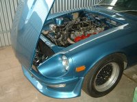
I got a good 280bhp from 2.8 litres (6 cylinders) at about 7000rpm in my 260Z coupe, putting the car in the 12 second standing ¼ mile bracket. Fully (and I mean fully) ported cylinder head (and intake manifold), OS valves, triple DCOE45 Weber carbs, a rather wild cam and a big, free flowing single exhaust is all it took. Had a real nice, broad spread of torque too, happily pulling hard from well below 3000rpm. Would do 155 mph, redlined in 5th before I put a 4.625:1 diff in it to give a better launch off the lights.
I’m currently rebuilding the Zed’s engine to run on LPG though, with my own custom intake manifold design.
Here’s my daily driver:
http://users.picknowl.com.au/~glenk/COMM.HTM
The 5.1L engine makes a good 250kW / 600Nm on LPG with a stock bottom end – just ported the heads and intake manifold, fitted a rather mild hydraulic cam and a big 3” single exhaust system. The car is good for an easy low 13 sec ¼ mile pass, flat 13’s ideal (car only weighs 1350kg – that’s 45kg less that a current Subaru WRX, for example [The Zed weighs 1080kg]).
The intake, heads and exhaust still flow a much greater capacity than what’s being taken advantage of though with the current displacement and camshaft.
I’m currently organising the parts for 383 cu in stroker kit, 10:1 comp and a much hotter solid lifter camshaft, with a reasonably modest duration, but a very high lift and very high velocity ramp rates, for heaps of bottom end torque.
350kW and +800Nm should be on the cards when it’s finished.
Cheers,
Glen
2 litres is still a bit small for +300bhp normally aspirated. It would be possible, but you’d have to absolutely rev its tits off.
I got a good 280bhp from 2.8 litres (6 cylinders) at about 7000rpm in my 260Z coupe, putting the car in the 12 second standing ¼ mile bracket. Fully (and I mean fully) ported cylinder head (and intake manifold), OS valves, triple DCOE45 Weber carbs, a rather wild cam and a big, free flowing single exhaust is all it took. Had a real nice, broad spread of torque too, happily pulling hard from well below 3000rpm. Would do 155 mph, redlined in 5th before I put a 4.625:1 diff in it to give a better launch off the lights.
I’m currently rebuilding the Zed’s engine to run on LPG though, with my own custom intake manifold design.
Here’s my daily driver:
http://users.picknowl.com.au/~glenk/COMM.HTM
The 5.1L engine makes a good 250kW / 600Nm on LPG with a stock bottom end – just ported the heads and intake manifold, fitted a rather mild hydraulic cam and a big 3” single exhaust system. The car is good for an easy low 13 sec ¼ mile pass, flat 13’s ideal (car only weighs 1350kg – that’s 45kg less that a current Subaru WRX, for example [The Zed weighs 1080kg]).
The intake, heads and exhaust still flow a much greater capacity than what’s being taken advantage of though with the current displacement and camshaft.
I’m currently organising the parts for 383 cu in stroker kit, 10:1 comp and a much hotter solid lifter camshaft, with a reasonably modest duration, but a very high lift and very high velocity ramp rates, for heaps of bottom end torque.
350kW and +800Nm should be on the cards when it’s finished.
Cheers,
Glen
Attachments
JinMTVT said:I would like to know if anyone of us here,
as worked with accoustical knowledge, on engine tunning of intake to exhaust systems ??
I have read multiple books
( probably near 50 now ... )
On application of fluid mechanics and such to design and or tunning of engine components ,
and i have yet to see one that talks about the accoustical theory part of waves for tunning ...
they all state the obvious base that waves are created then propagated , and used for tunning ..but never do they go in the path of actually telling how to use,
how to predict and or how to tune for ..
What i am talking about here,
is using waves tunning with intake part, camshafts timing and lift, piston speed, valves, exhaust port to headers collectorts to exhaust end ....
If no one has any experience with that ,
i'd like to have help on finding how we can use the accoustical stuff to work with engines ..
i'll have to get reading my Master Handbook of Accoustics...but even there, i recall reading the basis,
but not real exemples on how waves acts and bouces and all ...
thanks for any help 🙂
Consider that the air flow has a DC component plus an AC component due to the valve timing. Then take a look at the pipes from a transmission line perspective. You might find some interesting ideas from double stub tuning in microwave system design. I thought about this a lot back when I studied acoustical transmission lines and the electrical analogies since I was also interested in cars.
Pete B.
well ..we already have alot of bike engines that are near 200hp with only 1 liter ..
i don't see why a 2.0l wouldn't get near 300hp ?
that's only 66% of the power ...
we are currently working on an NA 2.0l engine
L4 for our only FWD race car ever,
wich will be a Prelude 2001
( best ever FWD chassis if you ask me .. unless you are allowed to modify suspension points )
We are going for a minimum of 325hp,
i don't expect to get much more than that,
but i wont put the engine IN the car until it makes 325hp on our dyno ...
( we are soon to build a big "dangerous" inertial dyno!)
it is based on a F20B DOHC JDM accord SIR-T engine,
wich is basicly a destroked H22 DOHC VTEC from prelude series ...
i have seen 300hp @ 8200rpm on a similar speced engine, and that was with only half of all the parts we are going to make custom for this baby ...
i want to tune it all for peak torque @ 8500rpm approx
with a max rev set @ ~10500rpm
( we require ~195lbs torque to make our goal ...
stock engine in prelude makes ~165lbs torque untouched...but at 5200 rpm i believe )
it should be featuring alot of our engine prototype products 🙂
the key for high rpm power on those engine, is to reduce total friction as much as possible ...we will work alot on that matter!
SO BACK TO ACCOUSTICS 🙂
JinMTVT said:well ..we already have alot of bike engines that are near 200hp with only 1 liter ..
i don't see why a 2.0l wouldn't get near 300hp ?
that's only 66% of the power ...
Oh, it’s certainly doable, don’t get me wrong, I’m just saying that you’ll need lots of revs if you want to keep it normally aspirated.
Some of those ~1L superbike engines really spin – 15,000rpm+
Could you shoehorn a turbo SR20 into that Prelude? 🙂 😀 (only joking).
I’d recommend sending these guys a letter about the information you're after (although you’ll probably have to subscribe to get a reply):
http://autospeed.drive.com.au/
Cheers,
Glen
didn't bring up anythign special
If I do a search at
http://ep.espacenet.com/advancedSearch?locale=en_ep
I get about 4500 entries for this patent classification ( F02B27 ) dealing with just such things.
The disadvantage of patents is that they don't have to be written for Joe Average, they have to be written in a fashion that they are understood by "those known in the art".
Regards
Charles
- Status
- Not open for further replies.
- Home
- General Interest
- Everything Else
- Applying accoustical theories for combustion engine tunning ..