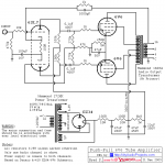
I have built the amplifier in the attached schematic as it seems to be popular and rather a simple design. I substituted a 12ax7 in place of the 6sl7 in the schematic. Only bad thing is it oscillates like crazy! After the tubes warm up there is a squeal and then it drops into about a 20hz oscillation. If I pull the 12ax7 all is quiet.
I have been through everything more times than I can remember and I’m finding nothing.
Any ideas? Fire away.
I have been through everything more times than I can remember and I’m finding nothing.
Any ideas? Fire away.
Attachments
6SL7 has a mu (voltage amplification) of about 70. 12AX7 is 100. Problem could be from too much gain destabilizing the loop.
Your output transformer is likely connected backwards, since this is a UL amplifier you can either swap the connections to the control grids of the 6V6s or you can swap both the screen grid and plate leads from one 6V6 output tube to the other.
Note you can replace the 12AX7A with a 5751 if the higher mu causes stability issues or you can change the feedback resistor to boost the closed loop gain a bit and improve the stability margin.
Note you can replace the 12AX7A with a 5751 if the higher mu causes stability issues or you can change the feedback resistor to boost the closed loop gain a bit and improve the stability margin.
My experience of the 12AX7 has always been poor.
I designed one into the front end of a guitar valve amp and it was unstable and noisy.
I just couldn't get rid of the instability despite careful circuit layout etc.
So I popped in a 12AU7 and it was great.
I designed one into the front end of a guitar valve amp and it was unstable and noisy.
I just couldn't get rid of the instability despite careful circuit layout etc.
So I popped in a 12AU7 and it was great.
I've built hundreds of amps with 12AX7A in them as well as several dozen pre-amps and have never had any stability issues. I did have problems with a literal breadboard, and that was solved by placing 220 - 1K grid stoppers right at the socket, literally mm away.
Millions of consumer tube hifis were built with 12AX7A/ECC83 just about anywhere you can imagine and they all worked fine.
Everything from Mullard 5-20s, to HH Scott, Fisher, Harman-Kardon, Leak, Avantic Beam Echo, EMI, Dynaco, not to mention countless Japanese, Dutch, Scandanavian products, tape decks - My ReVox G36 had scads of those in it, etc..
All my amplifier attempts jump up and down like a Scotchman in front of a pay toilet, and my oscillators just lay there. Dammit! I got it backwards.
I've built hundreds of amps ..
Maybe I was just unlucky and got a bad valve ?
It was many years ago but what appeared to be happening was two gain stages in the 12ax7 seemed to be feeding back from 2nd stage to first grid.
I tried decoupling both stages and that didnt fix it.
Sadly I cant find the circuit now so maybe it was simply lack of grid stoppers.
I must have designed about 20 valve amps and mixers since and not a 12ax7 in sight.
I have a Simms-Watts amp that uses 12ax7 but they have always put the two triode's in parallel ? so maybe they had problems too ?
I also think it is simple because the OT is connected backward.
OP swap the plate/UL taps to the other 6V6 and I am pretty sure it will work like a charm.
OP swap the plate/UL taps to the other 6V6 and I am pretty sure it will work like a charm.
I’ve had bad luck with some AX7’s. Most recent was a Philips ECG JAN12AX7A that produced the most horribly unbalanced concertina stage I have ever seen in my life. I’ve also had those damn Philips short out before, causing collateral damage, so I should have expected some misbehavior, but this is supposed to be foolproof. Stuck in a Sovtek and it was much better on the balance, but I’ve still got a motor boating issue when B+ goes above the Vg2 (When Vg2 actually goes into regulation). I don’t have that issue with a similar input stage using a 5751 on a much bigger amplifier. Low frequency loop gain may just be too high with an AX7. The OP’s circuit can’t have enough loop gain to oscillate if it doesn’t have a driver stage - unless the transformer is backward.
The B+ that runs the input stage must be very well isolated from the B+ that runs the output stage.
It is not well isolated.
And a 12AX7 does have more gain than the 6SL7, which makes it even more of a problem.
Any signal current load from the output stage across the 47uF B+ cap will cause the 47uF to have a voltage across it.
That voltage goes through the 6800 Ohm resistor to the 22uF input stage B+ cap.
At 20Hz, the 6800 Ohm and 22uf will only reduce the signal voltage from the 47uF cap by 18.8:1 at the 22uF cap.
That is a prescription for possible motor-boating.
Try increasing the 22uF cap (try paralleling it with an additional cap, 47uF or even better, a 100uF cap).
If you lift the negative feedback then the gain goes way up.
In that case, the input wiring must not pick up even the least amount of signal from the output wiring.
Or you might get another oscillator.
Also, you may have a B+ ground loop.
Connect the high voltage secondary center tap to the negative of the first filter cap.
Connect another wire from the negative of the first filter cap to the negative of the second filter cap.
Connect another wire from the negative of the second filter cap to the negative of the third filter cap.
Then connect the negative of the third filter cap to the bottom of the output secondary common (this is the common of the negative feedback that runs the 12AX7 cathode circuit.
The bottom of the output stage's self bias 250 Ohm resistor and 47uF cap negative needs to be directly connected to the negative of the 47uF Output stage's B+ filter cap.
Instead, if you just connected them all together another way, you could get an oscillator, and/or you can get hum.
Last edited:
It won't be that high as there is some other feedback from between the anodes of the phase splitter.
One more thing, the 47k resistor terminates the two 270k resistors.
But that means it controls the signal division for the grid of the 2nd triode in the input stage.
So, the other end of the 47k needs to connect to the negative of the 22uf input stage B+ cap.
The input stage (phase splitter) has a gain of about 50. It does not take much of a ground loop
or other related problem to make the amplifier not work.
The 6V6 in Ultra Linear at 40% tap gain is perhaps 35.
That would make the total gain about 1750 before the output transformer reduces the total input to output gain due to the turns ratio.
Plenty of gain.
Ground loops will make a good amplifier bad . . .
Oscillation, and / or Hum.
There are lots of items that can make an amplifier not work properly.
Is the output transformer the same as in the schematic?
Has this schematic ever been tested with that transformer (it is an old schematic, before that hammond transformer ever existed).
I believe it was originally made for use with an Acrosound transformer.
Are all the parts other than the 12AX7 exactly the same as in the schematic?
Attention to detail is the key.
When you get it working, Please let us know what you did, OK?
Last edited:
Ok so I feel like a total goon. The OPT was in fact connected backwards. Thanks Kevinkr!
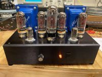
After swapping plate and grid leads all is well and the amplifier is dead quiet. Sound is very nice. Open and detailed. I am very happy!
On the scope it looks good. I fed it all kinds of sine waves and it reproduces all of them very clean.
The chassis is actually re purposed from an old fluid flow meter unit that was scrapped. It actually turned out to be perfect size!
Attachments

- Home
- Amplifiers
- Tubes / Valves
- Apparently I’ve built an oscillator.