I would like to ad an over load short circuit protection to the apexaudio Regulated PSU for my Bench power supply.
I started and asked apex for advises in this thread but I thought that it will be better to start an new thread in the power supply forum.
Thanks steveu who help all ready.

I was also thinking that may be better to have a circuit base of the new transistor biased by a voltage divider network.
Do you thing that is correct like that. Please advise !!!
I started and asked apex for advises in this thread but I thought that it will be better to start an new thread in the power supply forum.
Thanks steveu who help all ready.
I was also thinking that may be better to have a circuit base of the new transistor biased by a voltage divider network.
Do you thing that is correct like that. Please advise !!!
Question:
Why would you use such crap as a bench power supply?
There are lots and lots a bench supply schematics, why use this nonsense?
Why would you use such crap as a bench power supply?
There are lots and lots a bench supply schematics, why use this nonsense?
I did not expect this kind of question, but that still an advice somehow.
i am very happy with this design and I hope for something more appropriate regarding the add-on (Overload and Short-Circuit Protection) to the existing design
i am very happy with this design and I hope for something more appropriate regarding the add-on (Overload and Short-Circuit Protection) to the existing design
I have become addicted to my lab bench power supply's adjustable current limit feature, couldn't imagine living without it. Same for having four digital panel meters: Vout+, Iout+, Vout-, Iout- . The circuit in post #1 lacks these features and so it's not for me; but, to each his own.
I'm concerned that the "error amplifier" part of the regulator has relatively little gain (compared to other voltage regulator designs), so its "load regulation" (dVout / dIout) will be relatively poor. It appears possible to drastically increase gain by cascoding the NPN, and replacing its 220R collector load resistor with a current regulator diode (examples) .
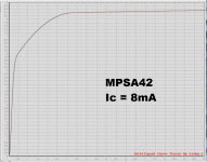
Finally the red MPSA42 might want to be a different part number, the 'A42 suffers from relatively severe quasi saturation. Measured IV data attached.
_
I'm concerned that the "error amplifier" part of the regulator has relatively little gain (compared to other voltage regulator designs), so its "load regulation" (dVout / dIout) will be relatively poor. It appears possible to drastically increase gain by cascoding the NPN, and replacing its 220R collector load resistor with a current regulator diode (examples) .
Finally the red MPSA42 might want to be a different part number, the 'A42 suffers from relatively severe quasi saturation. Measured IV data attached.
_
Attachments
I'm sure you didn't but sometimes one has to say what people need to hear, not what they want.I did not expect this kind of question, but that still an advice somehow.
And that presumptuously called "regulated supply" is just a grose improvisation, is has way to many issues to be worth discussing it.
Even a jellybean opamp like LM358 with some voltage reference and one darlington power transistor would do a much, much better job as a bench power supply.
this will likely work OK for a supply for testing different kinds of amplifiers, but is not a Bench power supply.
You need to add a couple diodes over the pass transistors to protect them against reverse polarity. Also add a diode over the output so that the supply can be put in series.
I would caution against using 10mF on the output as it negates most of the benefits of the current limit,
You need to add a couple diodes over the pass transistors to protect them against reverse polarity. Also add a diode over the output so that the supply can be put in series.
I would caution against using 10mF on the output as it negates most of the benefits of the current limit,
