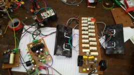
Hello friends... I have just build up APEX BA1200... sounds good thanx to Sir Mile from APEX AUDIO....
but there is unstabe offset at output... offset get from 0 to +/- 2volts and get increase....
Currently using only running on 2 pairs for o/p staging and 52 0 52... vdc
I have changed the bias resistance from 4.7k to 8.2k...... bias is ok
I have tried trimmer pot to adjust the offset but didn't help...
Any suggestions....
REGRETS....
Last edited:
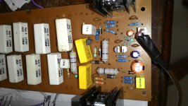
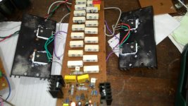
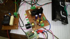
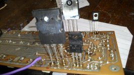
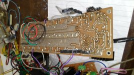
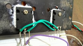
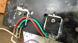
Photos of current setup... running ok but offset problem
Attachments
-
 P_20150705_114528_NT.jpg694.4 KB · Views: 450
 -
 P_20150705_114501_NT.jpg608.1 KB · Views: 412
 -
 P_20150705_114512_NT.jpg565.1 KB · Views: 383
 -
 P_20150705_114520_NT.jpg621.7 KB · Views: 378
 -
 P_20150705_115123_NT.jpg579.7 KB · Views: 358
 -
 P_20150705_115134_NT.jpg638.4 KB · Views: 218
 -
 P_20150705_115255_NT.jpg602.7 KB · Views: 167
 -
 P_20150705_115309_NT.jpg648.3 KB · Views: 161
Last edited:
At the very least, I would expect this setup to be highly thermally unstable:
1. The input transistors (MPSA) are not thermally coupled.
2. The bias transistor (BD681) is meant to be mounted on a common heatsink with drivers and outputs. Employ adequate insulation.
3. The original design specifies 1R0 emitter resistors, you used 0R47.
The flying leads could probably be optimized but don't look so long that I'd expect trouble with oscillation right away. Even if you don't have a scope, a simple "RF nose" (AC-coupled half-wave rectifier using Ge or Schottky diode) for the multimeter may be useful.
At the very least, I would expect this setup to be highly thermally unstable:
1. The input transistors (MPSA) are not thermally coupled.
2. The bias transistor (BD681) is meant to be mounted on a common heatsink with drivers and outputs. Employ adequate insulation.
3. The original design specifies 1R0 emitter resistors, you used 0R47.
The flying leads could probably be optimized but don't look so long that I'd expect trouble with oscillation right away. Even if you don't have a scope, a simple "RF nose" (AC-coupled half-wave rectifier using Ge or Schottky diode) for the multimeter may be useful.
Sir thanx for your suggestions
This Setup is temporary for testing ,1ohm would be high value so i used 0.47ohm ....
but it seems that there is some thing problem with mpsa92 ....
Does the problem occur because of the mpsa92 thermal characteristics
or any othere thing of the transistor...
Does 2N6520 (PNP) High Voltage Transistor will work on this ckt
Regrets..
- Status
- Not open for further replies.