OK so i just built the Apex AX6 amp. Link here - http://www.diyaudio.com/forums/solid-state/236256-retro-amp-50w-single-supply.html
1. Now the problem is that there is a persistent hum and the hum gets amplified with every bass beat and then settles down. Can anyone tell me what could be the issue.
2. Also i was thinking of putting a 4.7k resistor in parallel with the inputs to reduce the input impedance,reduce hum and ensure stability. Would this be a good idea ?
Any help would be appreciated...
Thanks
Some more details on the build please. Are you using one of Apex' board layouts (which post#)? If not, what does yours look like? What's your power supply like? Pictures? Does idle current seem OK? Does shorting the input make any difference?
It sounds like a bad PSRR problem in any case. Could be bad layout / grounding or woefully undersized power supply, or a bad solder joint at the 10µ or in the power supply. The circuit as designed should have decent PSRR.
BTW, an amp like this should really have a Zobel network at the output.
It sounds like a bad PSRR problem in any case. Could be bad layout / grounding or woefully undersized power supply, or a bad solder joint at the 10µ or in the power supply. The circuit as designed should have decent PSRR.
BTW, an amp like this should really have a Zobel network at the output.
Last edited:
This is the one I have used. Here's the link -http://www.diyaudio.com/forums/solid-state/236256-retro-amp-50w-single-supply-18.html#post3982525
Post by olafk...layouts are a couple of posts below.
At the power supply I have put a 4700 uf cap, parallel to the 2200 cap. It did seem to help a bit but nothing major. The power supply transformer is 35-0- 35.
The idle current looks ok and transistors (3773) run pretty cool. Also the sound distorts when the volume is increased. I haven't used a preamp and this amp runs directly from my ipod.
Just that you know..the hum is barely audible at no signal. It only starts when the music starts to play.
Last edited:
I built an AX6. It is so quiet you have to stand next to the speaker to hear anything with no input.
I built on Nema CE laminate, point to point. The output transistors are TO3 on a heat sink 15 cm away by wire from the driver baord.
Sound is very accurate.
I had trouble getting the center point voltage (output capacitor input) higher than 1/11 of the rail voltage, so I moved the collector of Q1 the input transistor to a diode above the emitter resistor of Q2 the VAS. I also adjusted the pulldown resistors on Q1 to move it up.
Rail voltage is regulated 70 v from 80v transformer. 5 TIP142 regulator pass transistors, .33 ohm emitter resistors, 1000 uf filter, 10 A fuse, 3300 uf capacitor, 2 driver boards (other is ST120 PC15 with djoffe bias mod). Used a .1 uf ceramic cap on the diode bridge output.
My chassis does have a zobel, 1000 ohm and some disc cap I can't remember. Also 15 turns wire around the output cap before the drive gets to it.
OT idle current set to 20 mv (40 ma) with music, but goes to zero in silent bands between the tracks of the LP.
I have 3 m RCA cables due to furniture and AC plug configuration, so I was getting radio stations when silent. Changing input cap from 22 pf to 68 pf fixed that. Now driving with ST33078 op amp mixer, but extra high input impedance should be compatible with 12AX7 drive preamp I own. Q1 is ON semi.
Q2 is genuine 1973 GE D44R2. Have a chinese house 2SC3423 via digikey to try the next channel, but it doesn't have a metal heat sink tab.
My chassis does have a zobel, 1000 ohm 3 w and some cap I can't remember on the output banana jack pair. Also 15 turns wire around the output cap before going into it.
Check your solder joint integrity. I trace music with a VOM on 2 vac scale and various capacitors on the negative probe.
Attachments
Last edited:
Reply to pm from Jrp27
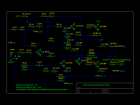
The zobel is on the schematic, 1000 ohm series 0.1 uf on the output side of the output capacitor. I think it is to keep the amp stable if the speaker is disconnected. also it plus the coil around the output capacitor keeps rf interference from bleeding in the speaker terminal and making the amp oscillate.
I can't check the printed board you used is accurate. Just buzz it (continuity check) to the printed AX6 schematic on the thread you listed. If you buzz on the component leads, you've just checked solder joint integrity.
The differences I report in post 4 were the ones I did to make it perform better. If center point TP2 is too close to rail or ground, it clips all the time when music is loud.
The AX6 doesn't have much supply rejection by design, so regulating the supply main voltage may be the reason you have hum and I don't. My chassis came with *****y supply regulation, the dynaco PC14, which I improved with the $6 circuit I detailed above. The bases of the darlington TIP142s were driven by five 1W 12V zeners stacked up arrow to line, with a 910 ohm resistor in series to limit current flow. The heat sink was from an old Pentium II mainboard, which was of course free since it was busted. I drilled and tapped the holes and salvaged heat sink pads. LED TV's are full of heatsinks too, I just scored a dozen at the curb on garbage day last summer. If your 35-0-35 transformer won't peak 80 v out of the bridge rectifier, you may need a lower voltage stack of zeners to drive the regulator transistors.
If regulated supply doesn't solve the problem, back to basic troubleshooting. DC voltages of collectors should be 1/3 to 2/3 of the rail voltage. B to E should be 0.6 v plus or minus. Resistors should have voltage drop, also capacitors. Look for the rediculous with a DC voltmeter. Then if that doesn't find the problem, trace music through with a sound probe to see where it starts sounding stupid. Sound probe is a variable gain amp with input protected by back to back LED's behind two 1000 ohm resistors.
Exercise with a cheap throwaway radio costing $2, not a $10-$700 cell phone. Use the earphone jack and turn down to about 1/4 volume, max volume on an earphone of a radio is about 7 vac. I fished my test radio out of the trash and put a new volume pot in it. The 1/8 phone to RCA plug adapter cost more than the radio, about $5.
Use cheap used car speakers (4 ohm or up) for testing these in case of blowups.
Reason I built an AX6 instead of a honey badger which rejects supply voltage variation, I had 8 cm x 13 cm to fit the board into. Also I solder every connection with a wire, so the fewer wires the better. I don't like polluting the ground or drain with FeCl waste, either here or in C****. Split supply amps also need add on protection boards to drive $600 (each) speakers, single supply amps with output capacitor do not. The great sound is in the speaker HD spec, not the 2nd and 3rd digit of the amp HD spec, IMHO.
Best of luck.
Last edited:
- Status
- Not open for further replies.