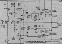
I would be very grateful if amp experts would take a look at this schematics and check it. I have -27 volts at the output (30 volts supply over security resistors). I was told that 82 ohms resistor in current source emiter should be about 1,2khoms but it didnt work.
Collector voltage on right current source is about -25 volts,collector-emmiter voltage on bias transistor is about 4 volts.
By regulating P1 i can trim output voltage for +- 6-7 volts.
If I set current over 350 mA output voltage drops down,but this is no A class schematics?
Any suggestions?
Collector voltage on right current source is about -25 volts,collector-emmiter voltage on bias transistor is about 4 volts.
By regulating P1 i can trim output voltage for +- 6-7 volts.
If I set current over 350 mA output voltage drops down,but this is no A class schematics?
Any suggestions?
Attachments
I severely recommend D.Selfs Power Amplifier Design Handbook.
There are many things wrong (well not right) with the design.
🙂 sreten.
There are many things wrong (well not right) with the design.
🙂 sreten.
It looks like it will work, but will be likely to oscillate without
an RC network to ground at the output, probably something
like .1 uF in series with 5 to 10 ohms (3 watt)
an RC network to ground at the output, probably something
like .1 uF in series with 5 to 10 ohms (3 watt)
P1 looks too big, a 1.2k resistor in series with a 1k pot will give a finer degree of adjustment. I think 1.2k in the second current source might be sufficient, 82 Ohm results in an unecessarily high current of around 14mA.
OK, i (mis) calculated that current would be 7 mA for 82 ohms ,and yes BC141 is maybe opened too much and therefore BD140 is opened all the time???
I tried to check with short circuited input and output voltage is still DC 27 volts.
I agree that this is simple shematics ,but to my experience it should work well .Checked PCB and all transistors but still -27 volts.Maybe base-emiter voltage on bias transistor is too high so it is saturated???
I tried to check with short circuited input and output voltage is still DC 27 volts.
I agree that this is simple shematics ,but to my experience it should work well .Checked PCB and all transistors but still -27 volts.Maybe base-emiter voltage on bias transistor is too high so it is saturated???
In the current sources you use two BC212 transistors and two 3k3 resistors and four diodes for setting the voltage of transistor bases. Try to exclude one 3k3 resistor and two diodes connected to the one transistor and then connect bases.
neuro_control said:I would be very grateful if amp experts would take a look at this schematics and check it. I have -27 volts at the output (30 volts supply over security resistors). I was told that 82 ohms resistor in current source emiter should be about 1,2khoms but it didnt work.
Collector voltage on right current source is about -25 volts,collector-emmiter voltage on bias transistor is about 4 volts.
By regulating P1 i can trim output voltage for +- 6-7 volts.
If I set current over 350 mA output voltage drops down,but this is no A class schematics?
Any suggestions?
the triple darlington connection is going to be very unstable at best. rule of thumb...don't put transistors in a darlington connection like yours if they do not have the same charactoristics.
They also must have the same temp. This is why they make integrated darlington pakages.
From what I see, the temp. coefficent is going to cause a thermal runnaway condition. (dead outputs is result.) Try using the current source to bias the drivers accros two series diodes. Then connect the outputs across these diodes and use a servo transistor to bias the drivers(which bias the outputs) adjustably.
The servo is mounted to the heatsink and turns off the outputs as it is heated by them. This makes for a stable temp. coefficent.
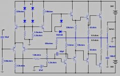
Travnic, i put the schematic to simulate
Sorry, not prevnin.
Simulator dislike the schematic... and the result was strange voltages.
This way, i go changing here and there... the result is showed.
This one, i create, is reasonable: do not like deep bass, and have not too much good relationship with top high frequencies.
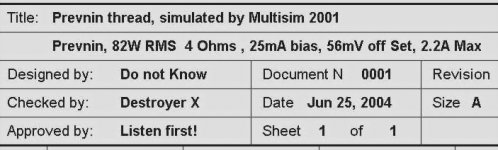
Square wave very bad under 400 hertz.... sinusoidal waves not perfect in 35 hertz, square and sinusoidal waves good shaped in 20 Khz.... 82 Watts founded, 2,2A each rail, 35mA bias and offset must be keept around 65 mV....because if you reduce....hummmmm unbalanced currents.
The differential resistors controls current to the positive (up)amplifier's side and negative(down) sides..... this way, reduce or increase a little to balance both currents...... also the 200 ohms resistor is very helpfull to achive this balance, better than the emitter one....... the differential emitter resistor, not more 1K8, can reduce to zero the off set voltage.....but no good reduce more than 50 mV.
Of course, this is simulation in Multisim 2001, and we cannot believe entirely.... only that the circuit works, and give us some idea of how it will work and the power achieved and voltages.
Cannot reproduce sound, cannot evaluate how it sounds, and cannot guarantee nothing.
I only trust it to give me this informations:
-Will work, will not work.
-May be good, may be reasonable, may be bad.
I never build one, that simulates bad ,and real world works!
I already assemble some amplifiers, that simulates good ,and sounds bad
Also assembled amplifiers that simulates reasonable, and sounds good
regards
Multisim 2001 file is here, if you want.
Carlos
Carlos
Sorry, not prevnin.
Simulator dislike the schematic... and the result was strange voltages.
This way, i go changing here and there... the result is showed.
This one, i create, is reasonable: do not like deep bass, and have not too much good relationship with top high frequencies.
Square wave very bad under 400 hertz.... sinusoidal waves not perfect in 35 hertz, square and sinusoidal waves good shaped in 20 Khz.... 82 Watts founded, 2,2A each rail, 35mA bias and offset must be keept around 65 mV....because if you reduce....hummmmm unbalanced currents.
The differential resistors controls current to the positive (up)amplifier's side and negative(down) sides..... this way, reduce or increase a little to balance both currents...... also the 200 ohms resistor is very helpfull to achive this balance, better than the emitter one....... the differential emitter resistor, not more 1K8, can reduce to zero the off set voltage.....but no good reduce more than 50 mV.
Of course, this is simulation in Multisim 2001, and we cannot believe entirely.... only that the circuit works, and give us some idea of how it will work and the power achieved and voltages.
Cannot reproduce sound, cannot evaluate how it sounds, and cannot guarantee nothing.
I only trust it to give me this informations:
-Will work, will not work.
-May be good, may be reasonable, may be bad.
I never build one, that simulates bad ,and real world works!
I already assemble some amplifiers, that simulates good ,and sounds bad
Also assembled amplifiers that simulates reasonable, and sounds good
regards
Multisim 2001 file is here, if you want.
Carlos
Carlos
Attachments
Have some to tell you, but cannot be openned to all forum
This one way communication, despite beeing good for one point of view, is no good in other point of view.
Nobody asked me, but i do not like this way, but can imagine hundreds of reasons to do this way.
If you want to here what i have to say, only to you, send me direct mail with your direct adress.
nanabrother@yahoo.com
Carlos😡
It will work. This is typical oldschool design, with old parts. With BD249C/250C gives some 80W into 4ohms, and will be reliable. I saw lot of similar designs. The sound is not so high quality, say "middle-fi"...
sajti
sajti
Satji, is incredible the way, we, you an me, all mankind, humans . We can be.....
Deeply rigth and deeply wrong same time.
Its a very simple school design (for you, your knowledge), this way you rigth
But the one that is having fun doing it, is deep skilled, full of knowlege guy...just having fun.
Thats my problem, maybe your too... so many times in this life i was deeply sure, and deeply wrong at same time.
Not ironic, not nervous, not kidding, not agressive, only comments about life....not more than that.
regards,
Carlos
"the triple darlington connection is going to be very unstable at best. rule of thumb...don't put transistors in a darlington connection like yours if they do not have the same charactoristics."
I did something like this a few weeks ago except that instead of connecting the emitters of the two left-most sets (pre-driver & driver) I to the output, I connected the left-hand pair only to the next levek base, and the middle pair emitters were connected the base of the next level and to each other via a 15k-ohm resistor and a 1uF bypass cap. The device pairs in acending order were 2n5551/5401, mje340/350 and 2sa1943/2sc5200. There was no sign of oscillation even putting varoius caps across the dummy load. Square waves were perfect.
As an epilog, I got too ambitious and decided to push things by successively reducing the value of the Cdom caps until I saw signs of oscillation. I went a little too far and . . . .POOF!
Oh yes. before messing with the caps I yanked the 2n551/5401s out and jumpered across as if they were not even there. Changed virtually nothing, leading me to suspect, that the tripple even if stable didn't contribute anything worthwhile.
- Status
- Not open for further replies.
- Home
- Amplifiers
- Solid State
- Anything wrong with this amp schematics?