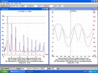
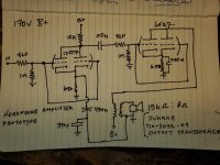
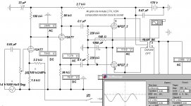
Here is a screen shot of the waveform & spectrum with PP 6V6s in that self inverting cct. Measured by a PicoTech 12-bit Scope/ Spec A. The cct performance would be much better if the PP stage was preceded by a real phase inverter.
The 6CG7 is electrically the same as a 6SN7 but can dissipate only 5W total as opposed to the 6SN7 7.5 Watts. Last year I ran a series of tests on twin triodes running PP Class A. The results with regard to power output are tied to the ability to dissipate heat. So for the 6SN7 that was one watt with a plate supply of about 300V. You could use one of your 12AT7s to form a proper phase inverter.
Also run in the same cct were 6BL7 & 6BX7, 3Watts. A friend donated a 5998 for the tests, it made an honest 10 Watts before clipping. The 5998 was originally designed for service in regulated power supplies, similar to the 6AS7G.
Attachments
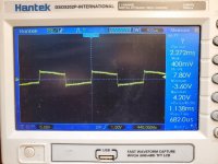
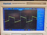
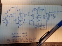
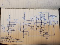
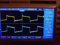
I tried a few things. Firstly, I attempted a "long tail pair." It worked and sounded nice but there was very little gain, even after using another triode before the phase inverter. I'm not sure where I went wrong. I didn't think to get it on the scope but it registered ~1v P2P on the output at full volume. Then I adapted the original design to (mostly) use Ketje's resistor suggestions. I used a 220k and a 270k resistor as I didn't have any 240k's on hand. I also adapted it to use a 6cg7/6fq7 for the PP output. No oscillation or overload, but I only got ~7v P2P on the output at full volume, even with an input gain stage made up of both sections of a 12at7 in parallel. Image of 440khz square wave follows. That's loud enough for most tracks (at least for my test headphones) but there is no headroom in case it's needed. I changed the values to 22k and 47k and got 14v P2P at full volume. Plenty of gain but I'll admit I don't yet fully understand what's happening in this part of the circuit. i.e. Those values may be a bad idea. Image of that 400khz square wave also follows. All attempts have been using 120vdc B+. I'm still playing with it. I'd now like to try a 12at7 as an input gain stage/phase inverter for each channel and send that to the 6cg7 in PP for the output. I also have a pair of 6GU7's. I gather that they're similar to the 6CG7 and they have the same pinout. They worked in the above tests bit with maybe a 10% drop in gain.
Attachments
I tried a new design with the same tubes. One 12at7 and 6fq7 per channel. Triodes in each tube running in parallel. I attempted to bias them correctly time but I'm having some trouble understanding exactly what does what. I'll figure it out eventually. I also added some negative feedback as shown in one of the previous schematics that I shared. It actually improves that sound and the scope waveform quite a bit. This one works with plenty of volume and the tubes don't get nearly as hot. The 6fq7 gets a bit uncomfortable but the 12at7 is just lukewarm. It sounds pretty good to my ear, but the scope looks almost identical to the images that I shared with my last post. What gives with that? Could it just be my output transformer or could some other design element be affecting it?
Attachments
The schematic that you have shows a cap from the grounded end of the OT back to the cathode of the first stage. That will not provide any feedback.
If you have a push-pull transformer, then you really don't want to use it as a series feed transformer, which is what you have drawn. Push-pull transformers do not have an airgap in the stack (99.999% of the time, I've seen it once!), so they saturate when you pull unbalanced DC current across the primary and performance gets yucky.
If you have a push-pull transformer, then you really don't want to use it as a series feed transformer, which is what you have drawn. Push-pull transformers do not have an airgap in the stack (99.999% of the time, I've seen it once!), so they saturate when you pull unbalanced DC current across the primary and performance gets yucky.
Well, it's technically not a PP or SE transformer. It's a line matching transformer. It has eight taps on the high impedance side. Maximum would be somewhere around 15-20k. They're $3 each and rated to four watts in their intended application. I'm amazed that they work at all to be honest As for the feedback, I forgot to include a resistor in the schematic and just now realised that I even have it hooked up wrong.. Thanks for the heads up.
I think line transformers are made for AC signals.
Unless the laminations are Air Gapped, it is not made for DC current that your SE amp output tubes are applying to the primary.
Saturation is very likely.
That would tend to give lots of slope to the 440Hz square wave you see in the scope traces.
Saturation intermodulates bass frequencies onto mid and high frequencies.
The scope traces also show some very high frequency riding on the 440Hz square wave.
Last edited:
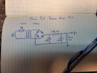
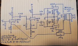
Okay, so one more question. I went through a couple of se configurations and then tried this push-pull design that I found over at Tube-Town. I think it's called Emma v1.3.31. (it's not in English) It'll never be "hi-fi" per se with these cheap opt's but it does actually sound pretty darn good to me now. Im still playing with it though. Anyway, I just omitted the front end since it was designed as a guitar amp and wired it for a 12at7 and a 6fq7 since thats what I've got on hand. I have two channels on the breadboard and it's an absolute rats best of leads. As on might expect, I'm picking up a tremendous amount of RF interference. That was previously pointed out in the scope traces but it's even worse now. Possibly due to there being more wiring and gain with this design. Aside from lead dress and shielding, is there any way I can help mitigate that by design? I just don't want to build a cabinet and get it all together just to be able to hear the hard drive in the computer kick on and seek every few seconds.
I've learned a lot during this project and I really appreciate you guys taking a moment here and there to give me some guidance.
I've learned a lot during this project and I really appreciate you guys taking a moment here and there to give me some guidance.
Attachments
The 22K grid stoppers on the output stage are not the best idea. A bypass cap across the cathode resistor at the output wouldn't hurt.
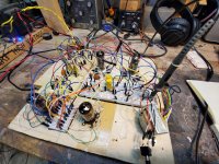
Try drilling out a cake pan and building up a prototype on that.
Try drilling out a cake pan and building up a prototype on that.
Looks like a very nice multi-frequency RF generator.
Probably OK after being stuffed into an Aluminum box with short leads.
Amazing what order can do.😀
Probably OK after being stuffed into an Aluminum box with short leads.
Amazing what order can do.😀
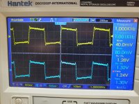
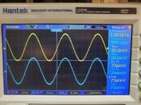
I omitted the grid stop resistors and added 330u cathode bypass caps on the two output triodes. I added some feedback, first testing resistance values with a pot to see where it would start oscillating. 6k ohm seemed to be about absolute minimum so I set it to 8.2k. Shielding the proto board with a grounded cake pan helped somewhat and using a shorter audio-in cable effectively eliminated the interference altogether. I guess short/shielded audio cables will be a must. I also tied both legs of the 6.3VAC to ground through 220R resistors. I saw that on several schematics during my research. I'm not sure what that's called, but it absolutely knocked out what little audible hum there was. I'll probably substitute the power resistor in the power supply section for a choke in the final build. Those cathode bypass caps along with the feedback helped flatten out the square wave considerably. I tried it with 6GU7s instead of the 6FQ7s and got similar gain, but the low end was muddy. Everything just sort-of mushed together and lost definition. Didn't care for them. I also tried it with 12AU7s in place of the 12AT7s and it sounded very similar, albeit with less volume as one would expect. I'd like to try it with 12AX7s but I don't currently have any. The signal traces in the image are of the right and left channels. They are wired identically so I'm guessing that the differences are due to the tubes not being matched. I'm seeing a bit of overshoot and ringing on both of them though. That is with the headphones plugged in. Not sure if it is noticeably affecting the audio or not. The sound at this point is absolutely fantastic, not that I'm any authority on the subject. Bass has filled out substantially without becoming muddy and treble is nice and crisp without being too harsh. Heaps and heaps of gain. I didn't know that triodes could pull all that off to be honest. I'm thoroughly pleased with how it sounds.
Attachments
There is an error in your schematic, the NFB lead needs to be moved back to the cathode of the previous stage, otherwise the phase inverter is unbalanced.
That's what I initially tried but I can't get it to stop oscillating when I hook it up like that to save my life. I've tried several cap sizes from 390 pF to 330 uF and resistance up to 50k to no avail. Also ran the cap to ground instead of putting it in series with the resistor.
No dice. Guess I'm just going to have to keep messing with it. About to go to bed but I'll try it again tomorrow. Enjoying my mandatory Covid Vacation this week.
No dice. Guess I'm just going to have to keep messing with it. About to go to bed but I'll try it again tomorrow. Enjoying my mandatory Covid Vacation this week.
If the cct oscillates only when the NFB is connected you may need to reverse the connexions from the 6FQ7 plates to the OPT.🙂
Simulation on the PP 6FQ7 Amplifier
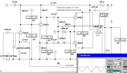
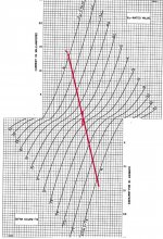
Here are two sims, one of which has a single 6FQ7 twin triode in PP driving into the Dukane OPT. The OPT looks like 19.6 K with an 8R load connected. A composite characteristic of the PP 6FQ7 with that loadline is attached.
Drive to the output pair is set to measure the audio power resulting when grid current has just started. To do that the scope is connected in the differential mode.
So for the single 6FQ7 that is ~340 mWatts. But the loadline impedance is not much different form the PP 6FQ7s as generators. So D% is bound to be high. Refer to the D% curve for an SE 6A3 in #15. This curve is representative of all common triodes. In the case of a PP amplifier the D is odd order (3rd, 5th, 7th, Etc), the kind people object too.
A 2nd 6FQ7 in the output section helps a lot. The audio power increases to ~530 mWatts with a substantial improvement in D%.
Better still would be to use twin triodes such as the 6BL7 or 6BX7.🙂
Attachments
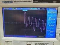
I'm gonna be honest.. A good deal of that shot right over my head..  I appreciate the effort to get through my thick skull though. I was planning on getting a matched set of tubes for the final build anyway so I may get some of the ones you suggested instead of more 6FQ7s. You were correct about reversing those leads. I was initially disappointed though because until I removed the capacitor in the feedback circuit, it still oscillated badly. From what I understand, it's there to prevent oscillation so I'm a bit concerned with leaving it out. I again tried several wide ranging values but got the same results each time. The square wave looks better still though. Gain dropped significantly but that's fine since there was a good bit to spare. I doubt seriously that I'm measuring it correctly, but I attempted to look at the output in FFT mode to see harmonics. My scope is one of the cheapest on the market but it's my first so I'm just happy to have one. My signal generator is a bit more high tech though. It's my old smartphone running an online tone generator. Turns out that the "ringing" is coming right from it. Input and output look identical as far as that goes. The signal trace image is of the left and right outputs. FFT trace is of one channel with a 1khz square wave. Sine, sawtooth and triangle all had lower peaks though I'm not sure how much any of that means considering my setup.
I appreciate the effort to get through my thick skull though. I was planning on getting a matched set of tubes for the final build anyway so I may get some of the ones you suggested instead of more 6FQ7s. You were correct about reversing those leads. I was initially disappointed though because until I removed the capacitor in the feedback circuit, it still oscillated badly. From what I understand, it's there to prevent oscillation so I'm a bit concerned with leaving it out. I again tried several wide ranging values but got the same results each time. The square wave looks better still though. Gain dropped significantly but that's fine since there was a good bit to spare. I doubt seriously that I'm measuring it correctly, but I attempted to look at the output in FFT mode to see harmonics. My scope is one of the cheapest on the market but it's my first so I'm just happy to have one. My signal generator is a bit more high tech though. It's my old smartphone running an online tone generator. Turns out that the "ringing" is coming right from it. Input and output look identical as far as that goes. The signal trace image is of the left and right outputs. FFT trace is of one channel with a 1khz square wave. Sine, sawtooth and triangle all had lower peaks though I'm not sure how much any of that means considering my setup.Attachments
Last edited:
Use a Square wave to testing for frequency response (downward slope, rise time, and "ringing"). you did that in your left screen shot.
A square wave is not good for doing a harmonic distortion test, because it has all the odd harmonics, that get in the way of trying to measure the amplifiers harmonic distortion:
Fundamental 0dB (reference)
3rd Harmonic - 9.5 dB
5th Harmonic - 14 dB
7th Harmonic - 16.9 dB
9th Harmonic - 19.1 dB . . .
Etc.
The sine wave is good for harmonic distortion testing. Use a 1 kHz sine wave.
Suppose the 2nd harmonic (2kHz) is 40 dB lower than the fundamental, and the 3rd harmonic (3kHz) is 40 dB lower than the fundamental, and you do not see any other harmonics.
In that case, the total harmonic distortion is 1.4%.
Or suppose the 2nd and 3rd harmonics are each 34 dB below the fundamental. That would be 2.8% harmonic distortion.
Please show us an FFT screen shot of a 1kHz sine wave from the amp.
Last edited:
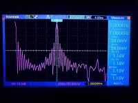
Whatever scope settings you had for the square wave, was a better scope setting than you had for the sine wave.
But it appears that the 2nd harmonic is -26dBc, and the 3rd harmonic is -30dBc, and some higher harmonics at lower levels.
That is about 6 or 7% harmonic distortion.
You need to learn how to set your scope and FFT, to be more sure of that kind of measurement, because the
scope time domain traces look more like only about 1% harmonic distortion.
Last edited:
- Home
- Amplifiers
- Tubes / Valves
- Anything inherently wrong with this design?