Hi guys ! i though i drop in , it has been a long time hearing from allot of you guys!!, i did not fall off the planet either.. but kept making stuff and posting it on youtube. and since most of the the knowledge about weird designs is here !! i though i might want to look at this section up more often again !. since everyone helped out on many problems i had !
here is some stuff i was working on, mostly playlists.. so im sorry it is rather much 🙂
- Headphone planar magnetic driver
YouTube
- My older fullrange planar magnetics
YouTube
- Small planar magnetic bluetooth speaker
YouTube
and much more like neodymium tweeters but i never made a playlist of the 30 versions i made.... 🙁
aaah well anyhow ill try to be more active again on here , since when i looked back i really enjoyed all the good advice and conversations we had!
Hi Joppe, I really appreciate your videos. I check in every once in a while to see what is new. Keep them coming ! 🙂
I have experimented with many of the 'weird designs' found in this forum - BMLs, neo ribbons, neo planar magnetics, Walsh cone style, rubanoide, etc. I enjoy building new things but I haven't really done an all out serious build though. I like the idea of the rubber mag strips you used. I'll likely give that a try once I run across a source with the correct field orientation.
Cheers,
Thanks cubby !! Yeah i got the same i tend to never make it in a permanent project but often a test a try an idea 🙂 but who knows 🙂 someday hihi
Joppe is exactly the person who inspired me to build speakers on the rubanoid principle.
It turned into over 50 different membranes and just as many voicecoils.
I then expanded with a fostex 12" (Edgeless) from 300 to 80 Hz and from 80 to 14 Hz 2 x 15" in closed chamber (one on the front and one on the back) with Motional feedback and it all active with DSP.
The Rubaniode get a little help from about 14 KHz from af AMT tweeter placed right under the Rubanoide. The AMT have a 0.5 uF capacitor in serie and parallel to the Rubanoide.
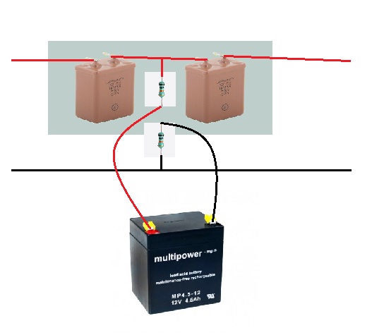
The capacitor are two Russian 1uF in serie and battery powered
Overall, it took about 1½ years to get this result which I am extremely pleased with, it is actually the best sound I have ever had
So thank you Joppe 😉
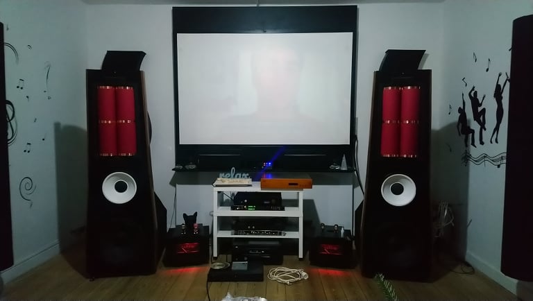
Heres some pictures
Measurement of both speakers from listening position
Red = Right
Green = Left

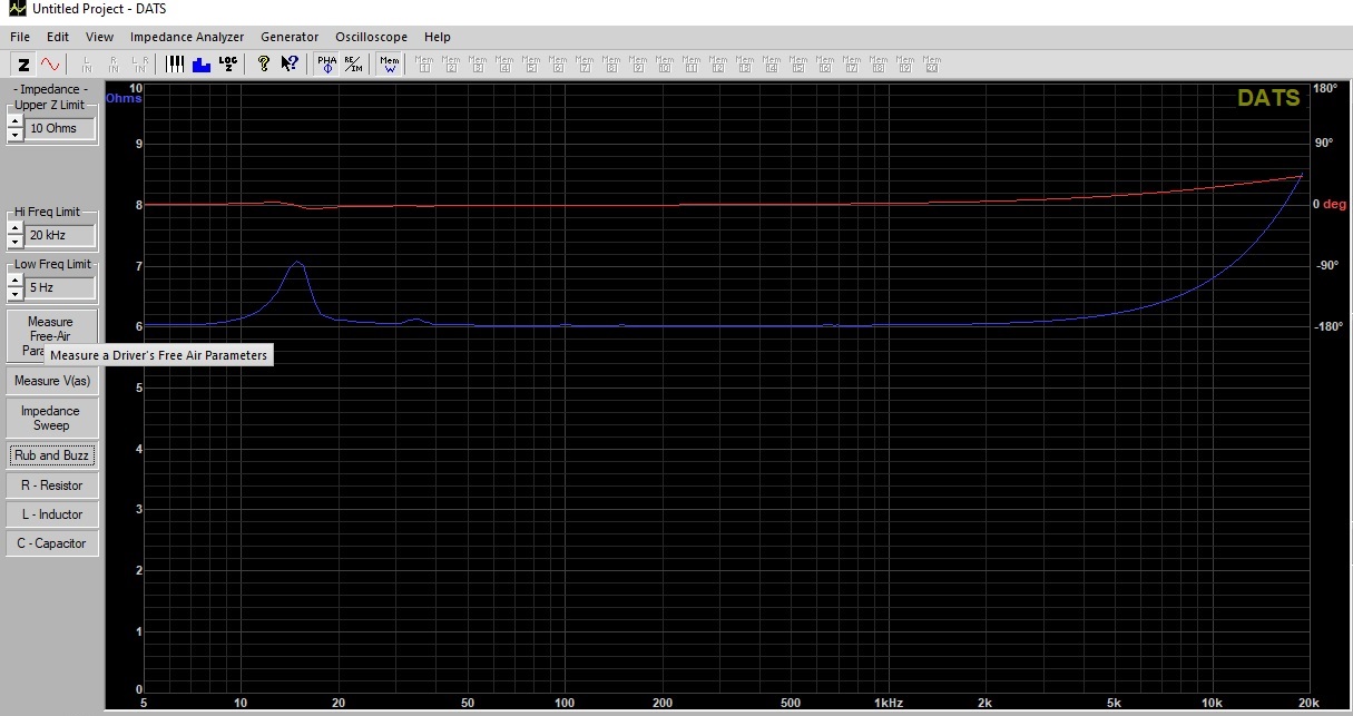
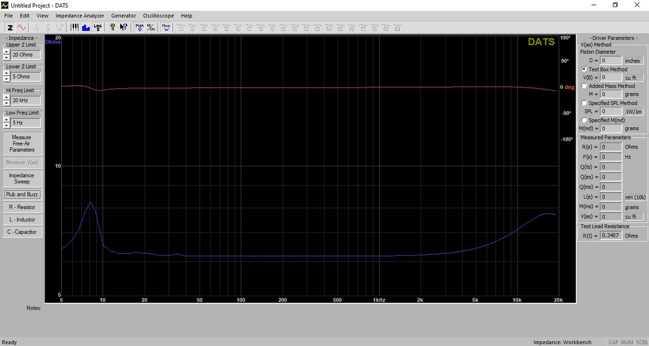
And here is a impedance and phase measurement of the Rubanoide
It turned into over 50 different membranes and just as many voicecoils.
I then expanded with a fostex 12" (Edgeless) from 300 to 80 Hz and from 80 to 14 Hz 2 x 15" in closed chamber (one on the front and one on the back) with Motional feedback and it all active with DSP.
The Rubaniode get a little help from about 14 KHz from af AMT tweeter placed right under the Rubanoide. The AMT have a 0.5 uF capacitor in serie and parallel to the Rubanoide.
The capacitor are two Russian 1uF in serie and battery powered
Overall, it took about 1½ years to get this result which I am extremely pleased with, it is actually the best sound I have ever had
So thank you Joppe 😉
Heres some pictures
Measurement of both speakers from listening position
Red = Right
Green = Left
And here is a impedance and phase measurement of the Rubanoide
Well thank you, by the way they look awesome besides being red 🙂 (not my thing ) i LOOooveeee the design of the cabinet !!! measurements looks great to !!! MFB nicee you build the mfb yourself ? or used an old one or bought a new version ? love mfb !Joppe is exactly the person who inspired me to build speakers on the rubanoid principle.
It turned into over 50 different membranes and just as many voicecoils.
I then expanded with a fostex 12" (Edgeless) from 300 to 80 Hz and from 80 to 14 Hz 2 x 15" in closed chamber (one on the front and one on the back) with Motional feedback and it all active with DSP.
The Rubaniode get a little help from about 14 KHz from af AMT tweeter placed right under the Rubanoide. The AMT have a 0.5 uF capacitor in serie and parallel to the Rubanoide.
The capacitor are two Russian 1uF in serie and battery powered. battery power ?? waht are you powering ?
Overall, it took about 1½ years to get this result which I am extremely pleased with, it is actually the best sound I have ever had
So thank you Joppe 😉
Heres some pictures
you said The capacitor are two Russian 1uF in serie and battery powered. battery power ?? what are you powering ? caps dont need power ? by the way the drawing makes a dead short 🙂 haha
Last edited:
you said The capacitor are two Russian 1uF in serie and battery powered. battery power ?? what are you powering ? caps dont need power ? by the way the drawing makes a dead short 🙂 haha
I think Infinity used batteries that way many years ago. Is there not something called biasing of capacitors? Maybe that is only for electrolytics?
Thanks Joppe
The battery to the capasitors is an old JBL "thing" and Primare uses it in Little 16 and Big 49 speakers too.
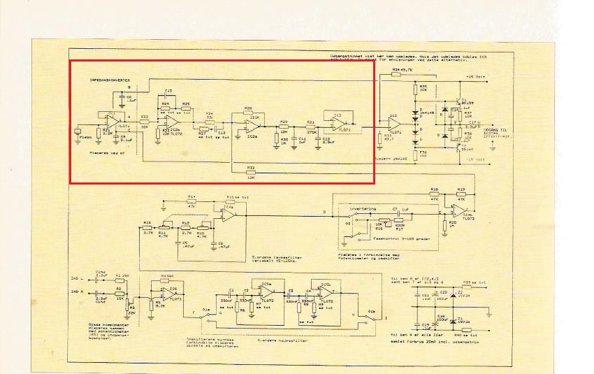
Is a pre bias "thing" and its not making ad dead short cause of two resistors 😛
L300 charge coupled crossover questions
The MFB is from a Danish magasin (High fidelity) and is easy to make and really cheap
Iam only using the components in the red square cause my pre amp and DSP can do the other things
The battery to the capasitors is an old JBL "thing" and Primare uses it in Little 16 and Big 49 speakers too.
Is a pre bias "thing" and its not making ad dead short cause of two resistors 😛
L300 charge coupled crossover questions
The MFB is from a Danish magasin (High fidelity) and is easy to make and really cheap
Iam only using the components in the red square cause my pre amp and DSP can do the other things
Last edited:
Thanks Joppe
The battery to the capasitors is an old JBL "thing" and Primare uses it in Little 16 and Big 49 speakers too.
Is a pre bias "thing" and its not making ad dead short cause of two resistors 😛
L300 charge coupled crossover questions
The MFB is from a Danish magasin (High fidelity) and is easy to make and really cheap
Iam only using the components in the red square cause my pre amp and DSP can do the other things
Aah thank for the paper to !!! I see i need glases i thought the 2 resistors where connected........ whoopsy theb it would be dead short. I myst not look at this kind of thing this early in the morning by the looks of it haha. Sorry 🙂
😀😀😀😀Aah thank for the paper to !!! I see i need glases i thought the 2 resistors where connected........ whoopsy theb it would be dead short. I myst not look at this kind of thing this early in the morning by the looks of it haha. Sorry 🙂
Hi skruerselv. Can you share some material/construction details about your red & copper membranes ?
I had settled on Japanese kozo paper treated with kakishibu for waterproofing, as an improvement over the original designers use of artist sketch paper. I'm really curious what you ended up with after trying 50 different materials.
If your speakers sound remotely as good as they look, you must be really content.
Thanks.
I can try 😀
The red paper is stiff 120g paper/carton ((i have tried lighter paper but it makes resonances), and there are 4 pieces glued on a voicecoil made of coated carton (Serimatt on Danish).
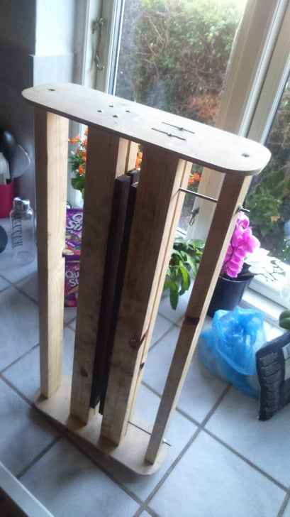
The voicecoil is made a little in a slightly special way. (the picture probably tells the most)
But there are snail tape cut into 2 mm strips that are placed in 2 x 5 on each side and all i serie (about 6 ohm) and a flat carbon fiber between for more vertical stiffness
I have soldered them together with the inner wire from CAT5 cable (stiff, thin and light weight)
The cobber on the red paper is a "design thing" but give the membrane a little more stiffness and are also snail tape
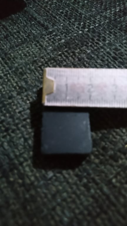
The nylon thread suspension is made with screw and nut so that it can be adjusted both for placement in the magnetic gap and FS
Important is where the membrane are mounted in the sides, i found the best sound with a soft window list and not pressed too much, it gives a god damping
The sensitivity are about 93 db (compared with my Fostex SLE34 in fullrange) and absolutely not as great as the original (105 db) But from the 300 Hz i use it, i can put more than 300 watt (6 ohm) in it without any problems.
I can get much greater sensitivity if i replace the ferritmagnets with neodymium, but i am happy as it is 😛
Heres some pictures, and ask all you want 😉 (Hope you understand my "excellent" English 😀😀
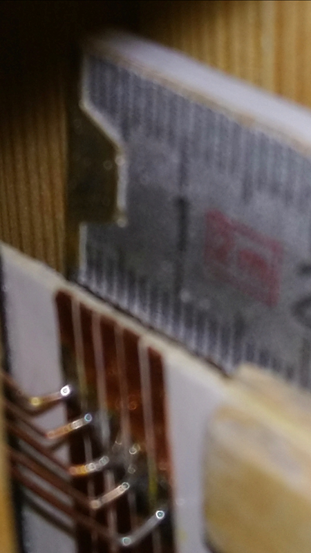
Voicecoil:
Snail tape
Cat5 soldering (Disregard my finger it has been in a milling machine) 😀
Nylon thread suspension (the picture here is one of the first attempts with that suspension so it looks a little fun)
Windows list
The red paper is stiff 120g paper/carton ((i have tried lighter paper but it makes resonances), and there are 4 pieces glued on a voicecoil made of coated carton (Serimatt on Danish).
The voicecoil is made a little in a slightly special way. (the picture probably tells the most)
But there are snail tape cut into 2 mm strips that are placed in 2 x 5 on each side and all i serie (about 6 ohm) and a flat carbon fiber between for more vertical stiffness
I have soldered them together with the inner wire from CAT5 cable (stiff, thin and light weight)
The cobber on the red paper is a "design thing" but give the membrane a little more stiffness and are also snail tape
The nylon thread suspension is made with screw and nut so that it can be adjusted both for placement in the magnetic gap and FS
Important is where the membrane are mounted in the sides, i found the best sound with a soft window list and not pressed too much, it gives a god damping
The sensitivity are about 93 db (compared with my Fostex SLE34 in fullrange) and absolutely not as great as the original (105 db) But from the 300 Hz i use it, i can put more than 300 watt (6 ohm) in it without any problems.
I can get much greater sensitivity if i replace the ferritmagnets with neodymium, but i am happy as it is 😛
Heres some pictures, and ask all you want 😉 (Hope you understand my "excellent" English 😀😀
Voicecoil:
An externally hosted image should be here but it was not working when we last tested it.
Snail tape
An externally hosted image should be here but it was not working when we last tested it.
Cat5 soldering (Disregard my finger it has been in a milling machine) 😀
An externally hosted image should be here but it was not working when we last tested it.
Nylon thread suspension (the picture here is one of the first attempts with that suspension so it looks a little fun)
An externally hosted image should be here but it was not working when we last tested it.
Windows list
An externally hosted image should be here but it was not working when we last tested it.
Last edited:
Good work!
I guess that the membrane is rather heavy?
Thank you 😉
With voicecoil the weight is 72 gr, and if i dont tightens the suspension up the FS is 8 Hz
Last edited:
I can try 😀
The red paper is stiff 120g paper/carton ((i have tried lighter paper but it makes resonances), and there are 4 pieces glued on a voicecoil made of coated carton (Serimatt on Danish).
The voicecoil is made a little in a slightly special way. (the picture probably tells the most)
But there are snail tape cut into 2 mm strips that are placed in 2 x 5 on each side and all i serie (about 6 ohm) and a flat carbon fiber between for more vertical stiffness
I have soldered them together with the inner wire from CAT5 cable (stiff, thin and light weight)
The cobber on the red paper is a "design thing" but give the membrane a little more stiffness and are also snail tape
The nylon thread suspension is made with screw and nut so that it can be adjusted both for placement in the magnetic gap and FS
Important is where the membrane are mounted in the sides, i found the best sound with a soft window list and not pressed too much, it gives a god damping
The sensitivity are about 93 db (compared with my Fostex SLE34 in fullrange) and absolutely not as great as the original (105 db) But from the 300 Hz i use it, i can put more than 300 watt (6 ohm) in it without any problems.
I can get much greater sensitivity if i replace the ferritmagnets with neodymium, but i am happy as it is 😛
Heres some pictures, and ask all you want 😉 (Hope you understand my "excellent" English 😀😀
Voicecoil:

Snail tape

Cat5 soldering (Disregard my finger it has been in a milling machine) 😀

Nylon thread suspension (the picture here is one of the first attempts with that suspension so it looks a little fun)

Windows list

Hahaha Nice i remember using this tape to, but this time when reading i was like wtf is snailtape. Hehe
Yep, snailtape sounds funny and its just coppertape, but it is really god to keep snails out of the garden 🙂 And excellent to voicecoils, haha
Impressive that you get 93 dB/ 1m!
Especially when you are not using Neos.
I guess that the gap is rather wide too as it seems that the voice coil isn't that thin.
What clearance has the voice coil to the gap?
Especially when you are not using Neos.
I guess that the gap is rather wide too as it seems that the voice coil isn't that thin.
What clearance has the voice coil to the gap?
In the picture it is at the beginning of the experiments with magnet distance, now the magnet gap is 4 mm and the voicecoil itself is 1 mm + cobber then about 1½ mm.
But I have 2 magnet rows on each side (one south and one north) to get more magnetic force and more copper in the magnetic gap
The size of the membrane are hight: 22 inch - Width: 11 inch
But I have 2 magnet rows on each side (one south and one north) to get more magnetic force and more copper in the magnetic gap
The size of the membrane are hight: 22 inch - Width: 11 inch
Ok, I see.
It looks like the coil is about the same width as the magnets then.
What Xmas does this yield?
What are your thoughts about that the magnetic field density is not that linear in the gap when using magnets directly?
It looks like the coil is about the same width as the magnets then.
What Xmas does this yield?
What are your thoughts about that the magnetic field density is not that linear in the gap when using magnets directly?
My pictures are not the best, i know 😀
But the voice coil´s copper is 10 mm widely and the magnet are 20 mm. So the voice coil can move +/- 5 mm and still be in the magnetfield/gab.
And it maybe moves 1 to 2 mm when i play really loud (+ 300 watt in the 6 ohm the Rubanoide are)
If the voice coil should move out of the magnetgab i have to play fullrange with them
- Home
- Loudspeakers
- Planars & Exotics
- Anything happening here ??