Large enough !
Hi Alastair,
We had quite nice weather in London, just a shower Saturday while eating in a restaurant !
So many miles in my shoes.
MPL is for "Magnetic Path Lenght", this should allow you to "measure" it.
But since your lams seem to be of the "scarpless" type, this value is simply 114/5, that is 22.8cms (a bit lower than for an EI120, of course).
Remember, an EI stack has two magnetic path so, the real thickness of the gap must be half the computed value because the flux crosses it twice !
If you have some difficuties, send me your "core.tbx" file.
Yves.
Hi Alastair,
We had quite nice weather in London, just a shower Saturday while eating in a restaurant !
So many miles in my shoes.
Looks large enought anyway.The bobbins are marked 120 x 2" BUT the lams that fit correctly, appear to be EI114--
If looking at a single lam, The longest side, is 114.3 mm
The centre limb is 38mm wide,
each side limb is 19mm wide
The height of the gap for the bobbin is 57mm
The stack height is 51mm, Hence the 2" marking on the bobbin
I think the confusion has arisen because I have an Imperial core, sort-of equivelent of a EI120B (closest listed to mine in the Calc program, the AFe is quite close)--Tried inputting the data for my core to the calc, but it wont accept it when doing calculation, and I dont know what MPL in mm means, so cant enter this value!
MPL is for "Magnetic Path Lenght", this should allow you to "measure" it.
But since your lams seem to be of the "scarpless" type, this value is simply 114/5, that is 22.8cms (a bit lower than for an EI120, of course).
Remember, an EI stack has two magnetic path so, the real thickness of the gap must be half the computed value because the flux crosses it twice !
If you have some difficuties, send me your "core.tbx" file.
Such old timers are usually of great help !I had a chat with my supplier, who has been in this trade for around 40 years, and described what I was up to--during the converstaion, I mentioned the word 'Inductance'--He looked square at me, and said--I dont 'Do' Inductance!--and being 'old fashoned, still works with Imperial sizes.--Even offered me a hand-winder, which I hope to collect Monday, proper counter fitted, big enough for any Tx I would ever need, but small enough to hide away when not in use. Cheap too!
Yves.
Glad the weather was fair for your break!
Yves, Take a quick look over this, if you have a miniute---
It has My EI114 core data--Or near enough!
[SPECIFS]
Freq=25
Watts=25
DCourant=2
Ip0=.20
Hys=126
Rp=80
Gap=.2
SE=1
Z0=600
Fract0=3
Fils0=1
Z1=8
Fract1=2
Fils1=4
[REMARQUES]
FreeText=Place to put remarks for this project
[CUIVRE]
Dia0=.55
Dia1=.55
[NOYAU]
Type=EI114
[ISOL]
Thickness=.5
DielectricK=5
[ZFPLOT]
0=20:8
1=60:8
2=200:8
3=6000:8
4=2000:8
5=600:8
6=20000:8
Looks like I can get two layers per section in .55 wire, four secondaries parralelled with .5 insulation Specs dont look too bad, What do you think?
(Be quite nice to use same guage for secondary as primary--Less to worry about, although I havent got the wire yet!)
Thanks, Alastair
Hi !
Looks good at a quick look, but send me the data for EI114 or the "core.tbx" file (it's a text file you can open with Notepad)) or just the pertinent line into.
Yves.
Looks good at a quick look, but send me the data for EI114 or the "core.tbx" file (it's a text file you can open with Notepad)) or just the pertinent line into.
Yves.
Core data
Hi Yves,
My core data as input into the calc is-
AFe 19.5
Mfe 3.5
mpl 22.8
Bobbin depth-17mm
Bobbin Width-51mm
mean turn length-23 cm
Still havent got the wire yet, been a bit hectic at work and havent been able to escape to play! (going to try and pick up the winder tomorrow though!)
If you have any better ideas as to the Tx, I would be pleased to hear them!
Thanks again,
Al
Hi Alastair,
No better idea, just tweeked a bit and added some comments.
http://perso.wanadoo.fr/yves.monmagnon/EI114-1.mox
WIND IT NOW 🙂
And tell me how that sounds !
Yves
If you have any better ideas as to the Tx, I would be pleased to hear them!
No better idea, just tweeked a bit and added some comments.
http://perso.wanadoo.fr/yves.monmagnon/EI114-1.mox
WIND IT NOW 🙂
And tell me how that sounds !
Yves
OK, OK, Ill wind it!
Guess I cant put it off any longer, so I had better get it sorted and wind the thing!
Thanks for all your great experience and help for this project, At least I know when its wound itll sound good, if not--better than good!
Still need to get away and pick up wire etc, If not later, definately tomorrow so as I can wind on weekend.😀
Its Wound, and working!
Well, that was a bit of a chore, but certainly paid off. No proper testing done as yet, but the sound is definately improved over the mains Tx I was using, especially in the lower frequency ranges.
Thanks again Yves, your input is greatly appreciated, and when I get the proper testing with sig-gen and 'scope done, Ill post them here. 😎
I just have 2 more to wind the same now...............
Alastair E,
Just got the message that my 2 James 6130H {for SE 6C33C-B}will ship tomorrow from Taiwan, could you give us a breif of the cost of such a great project for 2 OPT's.
Regards.
Alain.
Just got the message that my 2 James 6130H {for SE 6C33C-B}will ship tomorrow from Taiwan, could you give us a breif of the cost of such a great project for 2 OPT's.
Regards.
Alain.
Re: Its Wound, and working!
GREAT !
Since we cannot hear it, post measures ASAP
Yves (crossing fingers)
Alastair E said:Well, that was a bit of a chore, but certainly paid off. No proper testing done as yet, but the sound is definately improved over the mains Tx I was using, especially in the lower frequency ranges.
Thanks again Yves, your input is greatly appreciated, and when I get the proper testing with sig-gen and 'scope done, Ill post them here. 😎
I just have 2 more to wind the same now...............
GREAT !
Since we cannot hear it, post measures ASAP
Yves (crossing fingers)
Re: Re: Its Wound, and working!
It cost me £18 for three Bobbins, sets of laminations and transformer frames, and a rather nice 1000uF 400V cap that was lying round. The wire cost me £8.00 and the Mylar insulation if I recall correctly cost £2.50--More than I would ever use.
I need three finished Tx, as its to be used for the front channels in home cinema set-up.
Ill need to get my sig-gen back--Hopefully by the weekend.............

Alain Dupont said:Alastair E,
Just got the message that my 2 James 6130H {for SE 6C33C-B}will ship tomorrow from Taiwan, could you give us a breif of the cost of such a great project for 2 OPT's.
Regards.
Alain.
It cost me £18 for three Bobbins, sets of laminations and transformer frames, and a rather nice 1000uF 400V cap that was lying round. The wire cost me £8.00 and the Mylar insulation if I recall correctly cost £2.50--More than I would ever use.
I need three finished Tx, as its to be used for the front channels in home cinema set-up.
Yvesm said:
GREAT !
Since we cannot hear it, post measures ASAP
Yves (crossing fingers)
Ill need to get my sig-gen back--Hopefully by the weekend.............
Alastair E and Yvesm,
Next time I build one SE, I'll call you guy's to help me build my OPT's ;
you are doing a great job.
SE are done at lower cost using your software, thanks!
Yvesm, do you think that the OPT's needs immersion in shelac ?
Regards and 73's.
Alain.
Next time I build one SE, I'll call you guy's to help me build my OPT's ;
you are doing a great job.
SE are done at lower cost using your software, thanks!
Yvesm, do you think that the OPT's needs immersion in shelac ?
Regards and 73's.
Alain.
Alain Dupont said:Alastair E and Yvesm,
Next time I build one SE, I'll call you guy's to help me build my OPT's ;
you are doing a great job.
SE are done at lower cost using your software, thanks!
Yvesm, do you think that the OPT's needs immersion in shelac ?
Regards and 73's.
Alain.
Unless you live in tropical climat with 100% moisture, (or plan to use in a sauna) definitly not !
Yves
First testing-
Finally got my sig-gen back, and done some quick tests.
W/O Neg FB, 15Hz to 160KHz to -3dB
With Neg FB, 10Hz to 195 KHz to -3dB
This is at 20w into 8 Ohm non inductive WW resistor. The freq response is flat with no peaks at any points.
I have an issue with my driver stage at full O/P and lowest freq, that I need to sort out before I can give best performance figures. I'm able to get around 30W RMS before clipping at 1Khz.
Im unable to measture the THD, as i havent the needed equipment, but using the scope second channel superimposing the two sine waves, shows no visible differences.
More alterations and testing to follow.................
Re: First testing-
Hey, really not bad.
Even a bit better than expected at hi ends, means computations are a bit pessimistics, unless you changed interleaving or insulation thickness.
Please, let me know so I could revise some formulaes (their are of the "cook book" type and somewhat empirics).
Can you run a test with squares at say, 100, 1000 and 10,000 Hz ?
At lo end, the limiting factor is the iron saturation, I'm not sure it could be significantly improved, unless having twice as much iron !
Usually, sines become distorded, tweaking the gap may be instructive (note I don't say constructive).
If you have a correct sound board in your PC, Google for Spectra Plus, or any other spectrum analyser.
Cheers,
Yves.
Alastair E said:Finally got my sig-gen back, and done some quick tests.
W/O Neg FB, 15Hz to 160KHz to -3dB
With Neg FB, 10Hz to 195 KHz to -3dB
This is at 20w into 8 Ohm non inductive WW resistor. The freq response is flat with no peaks at any points.
Hey, really not bad.
Even a bit better than expected at hi ends, means computations are a bit pessimistics, unless you changed interleaving or insulation thickness.
Please, let me know so I could revise some formulaes (their are of the "cook book" type and somewhat empirics).
Can you run a test with squares at say, 100, 1000 and 10,000 Hz ?
I have an issue with my driver stage at full O/P and lowest freq, that I need to sort out before I can give best performance figures. I'm able to get around 30W RMS before clipping at 1Khz.
At lo end, the limiting factor is the iron saturation, I'm not sure it could be significantly improved, unless having twice as much iron !
Usually, sines become distorded, tweaking the gap may be instructive (note I don't say constructive).
Im unable to measture the THD, as i havent the needed equipment, but using the scope second channel superimposing the two sine waves, shows no visible differences.
More alterations and testing to follow.................
If you have a correct sound board in your PC, Google for Spectra Plus, or any other spectrum analyser.
Cheers,
Yves.
O/P Tx
For general info, here's how I wound the Tx's--(Ive finished all three now, and just need to sort out the PSU Tx.)
First layer, (First secondary) 85 turns, .56mm, just fits in on bobbin. This insulated first with layer of clear tape, of .05mm then a double layer of .11mm Mylar.
First section of Primary, with border between side of bobbin and start of coil of around 3mm, 61 turns by 4 layers, each insulated with single layer of clear tape then single layer.11 mylar 244 turns in this section, in .56mm.
(Borders are insulated with PTFE plumbing tape, and Anti-Track, Tx/Motor Varnish.)
Next, two layers of Mylar then second secondary, again 85 turns, then two layers Mylar, and one clear.
Second section of Primary, again 244 in four layers of 61 turns insulated by .11 single layer Mylar between layers, over single layer clear.
Then, third Secondary, insulated by two layers Mylar, of 85 turns.
Last Primary section built up as before, of 4 layers, at 61 turns each, with .11 Mylar single layer and clear, The last layer having an extra 5 turns equaling a total Primary of 737 turns.
Final Secondary of 85 Turns placed over last section of primary.
All sections of Primary series connected, and all Secondaries Parralleled.
Effectively, there are seven interleaves with the transformer, Three Pri, and 4 sec.
Testing was done by connecting Primary to 240v, all secondaries give 28 odd volts, but all are within .01V, All then attached in parallel, and one end earthed as was the laminations All transformers were left attached to 240v for an hour, No heating or earth leaks present.
Currently, using .2mm Air-gap, but Im going to try some experimenting to see the effects at low frequency. I currently have only standard laminations, as my supplier only had that size in standard--Hope to get some M6x soon, from a different supplier which should help the lower freq range power.
My sig-gen, only does sine and triangle waves, so cant check with square-waves, but will look at the suggested Software, if my Soundcard can cope, and check the distortion at rated O/P
Hope the info above is of help Yves, Thanks for your excellent help--There is no way I could have worked out the turns etc. Shows that the Calc works very nicely!
Whaou ! ! Great and Real DiY Job !
M6x accepts a bit more induction before it saturates, but when it does, it does it more abruptly.
Nobody's perfect !
By the way, I dont beleive you already published the schemo of your amp. Could you ?
Yves.
So, P to S insulation thickness is about 0.2 to 0.3mm ?For general info, here's how I wound the Tx's--(Ive finished all three now, and just need to sort out the PSU Tx.)
First layer, (First secondary) 85 turns, .56mm, just fits in on bobbin. This insulated first with layer of clear tape, of .05mm then a double layer of .11mm Mylar.
Mmmmh, It seems that your favorite provider gave you valuable tricks ! But, what is "Anti-Track" ?First section of Primary, with border between side of bobbin and start of coil of around 3mm, 61 turns by 4 layers, each insulated with single layer of clear tape then single layer.11 mylar 244 turns in this section, in .56mm.
(Borders are insulated with PTFE plumbing tape, and Anti-Track, Tx/Motor Varnish.)
Since the Mu of the iron is already "killed" by the gap, there is a very limited effect on primary L in using standard grade rather than M6X.. . .
Currently, using .2mm Air-gap, but Im going to try some experimenting to see the effects at low frequency. I currently have only standard laminations, as my supplier only had that size in standard--Hope to get some M6x soon, from a different supplier which should help the lower freq range power.
M6x accepts a bit more induction before it saturates, but when it does, it does it more abruptly.
Nobody's perfect !
By the way, I dont beleive you already published the schemo of your amp. Could you ?
Yves.
Schematic and other stuff....
The insulation is between .2 and .25 between Pri and Secondary sections. Each layer of Pri is insulated from the next by .15, made up of i layer clear tape and 1 layer Mylar.
Anti-Trak is some form of propriety varnish preparation a bit like real thick 'red-lead', I got some a while back when I was converting an Induction Motor into a generator and had to alter the windings for a different voltage. Motor Re-Winders use it to improve insulation of motor coils and to coat the insides of terminal boxes and the like Its Called, - 'UltiMeg 2000/372 Anti Tracking Varnish, Red' In spray-can like car paint--But smells nicer!Its made by, Advanced Electrical Varnishes, Birkenhead Merseyside, www.aev.co.uk
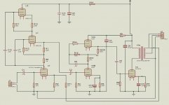
The attached schematic, is a work in progress, but is at the stage the amp is in real life--I need more +B at the driver, as Im getting a little distortion before full O/P of this stage--For normal listning levels, this is not apparent in the sound however. (Cant really notice it at high O/P either, but I know its there, and must fix it!) The O/P stage is very near at its max when the distortion form the driver becomes visible, and well over 25W RMS
Only real difference, is the O/P Tx shows a 4 ohm tap, which it doesn't in real life.
There is nothing original in this design, Ive blatently ripped off various stages from the Web, maybe with a few value changes to improve performance and to suit the valves Im using.....
Feel free to copy if you like............
Valve layout is, Top of twin-Mu stage, 6/30L2, gen purpose double triode--6DJ8 works just as well, but I have some nice NOS 6/30L2's and only well used Mullard 6DJ8's both have similar figures............
Bottom of first Mu stage, is ECC91 parrallel strapped double triode. Nice NOS Mullard ones.
Driver, is the venerable 6SN7 or at least its Russian analog...........
O/P is ubiquitous 6C33c-b--The rest you know........
To my 1961 ears, it sounds very nice, but perfection is in the ear of the beholder...........
The insulation is between .2 and .25 between Pri and Secondary sections. Each layer of Pri is insulated from the next by .15, made up of i layer clear tape and 1 layer Mylar.
Anti-Trak is some form of propriety varnish preparation a bit like real thick 'red-lead', I got some a while back when I was converting an Induction Motor into a generator and had to alter the windings for a different voltage. Motor Re-Winders use it to improve insulation of motor coils and to coat the insides of terminal boxes and the like Its Called, - 'UltiMeg 2000/372 Anti Tracking Varnish, Red' In spray-can like car paint--But smells nicer!Its made by, Advanced Electrical Varnishes, Birkenhead Merseyside, www.aev.co.uk
The attached schematic, is a work in progress, but is at the stage the amp is in real life--I need more +B at the driver, as Im getting a little distortion before full O/P of this stage--For normal listning levels, this is not apparent in the sound however. (Cant really notice it at high O/P either, but I know its there, and must fix it!) The O/P stage is very near at its max when the distortion form the driver becomes visible, and well over 25W RMS
Only real difference, is the O/P Tx shows a 4 ohm tap, which it doesn't in real life.
There is nothing original in this design, Ive blatently ripped off various stages from the Web, maybe with a few value changes to improve performance and to suit the valves Im using.....
Feel free to copy if you like............
Valve layout is, Top of twin-Mu stage, 6/30L2, gen purpose double triode--6DJ8 works just as well, but I have some nice NOS 6/30L2's and only well used Mullard 6DJ8's both have similar figures............
Bottom of first Mu stage, is ECC91 parrallel strapped double triode. Nice NOS Mullard ones.
Driver, is the venerable 6SN7 or at least its Russian analog...........
O/P is ubiquitous 6C33c-b--The rest you know........
To my 1961 ears, it sounds very nice, but perfection is in the ear of the beholder...........
Attachments
To my 1961 ears, it sounds very nice, but perfection is in the ear of the beholder...........
Add 15 for mine

Good looking schemo, but so many toobs !
With a local dude, we're looking to use a single EL802 (TV Video penthode, 40mA/V slope) to drive a 845 😱
But we have 1000V B+ available

Reports in few weeks, I hope.
Yves.
Never enough TOOBS!
Im actually thinking of adding another, similar to the first stage, but in the driver.............
Im actually thinking of adding another, similar to the first stage, but in the driver.............
- Status
- Not open for further replies.
- Home
- Amplifiers
- Tubes / Valves
- Anyone wound SE transformer for 6c33c-b?