https://www.parts-express.com/GRS-PT6816-8-8-Planar-Slim-Tweeter-8-Ohm-272-128?quantity=1
I had these on order for a short array project but they were on backorder for months so I cancelled…..notw they’re back in stock but I put that project on hold. My plan was an open baffle array from 800hz on up. Just wondering how they sound overall. The array would be 8 elements so I don’t think the 800hz crossover point would be an issue
I had these on order for a short array project but they were on backorder for months so I cancelled…..notw they’re back in stock but I put that project on hold. My plan was an open baffle array from 800hz on up. Just wondering how they sound overall. The array would be 8 elements so I don’t think the 800hz crossover point would be an issue

It looks like the response could fairly easily be shaped to flat out to 12k…..was that not the case in real use?
I use them, response to about 14kHz. Forum members said that is only good for hearing impaired, but I am happy anyways 🙂 I know of two other members that build line arrays, one with NEO 8 and the other with some other planars that have even less good HF response. They fiddled with additional tweeter arrays, but eventually gave up, so I never looked further.
I have 12 units per side, currently playing them with 2W from a 2A3 amp, so that is about 200mW per unit, I think that is what allows me to use them from 600Hz upwards and still sounding good. I choose 600Hz because I wanted to keep the distance to the woofers (cheap WS25e) smaller than 1/4 of the wavelength, probably could go higher, but then again I listen to it and forget about the rest 🙂
https://www.diyaudio.com/community/...ray-with-grs-slim-8-and-visaton-ws25e.364351/
You do not hear anything beyond 12k?It looks like the response could fairly easily be shaped to flat out to 12k…..was that not the case in real use?
There’s no fundamentals out past 12k, just archaic harmonics……..the only thing linear up there is electronic noise so I’m not picky about how to reproduce it. Super tweeters are fine but they do pose a problem for adding them to an array.…..and if there’s a -3db point of 15k, I won’t bother anyways.
It looks like they would be good as far up as one needs to go. The real questions are what to do on the low end and where to high pass them. If size and space aren't a concern, a pair of 15OB350 dipoles like in BitchesBrew would do nicely. Or 4 12OB150's like in CarverAmazing's from 45 years ago.
Now I recall....
About 5 years ago, I did a line array using small full range drivers. As part of that effort, I simulated an array of 16 of these 6816's using Vituix diffraction models. the axial response came out nicely flat but the vertical response was extremely sharp. It would have required vertical "head in a vise" listening. Even 10 degrees off vertical center had several big ( 5db or so) dips. If you look at the ratio of active membrane area to frame area, you will see that the mechanical construction doesn't allow getting units close enough together to approximate a continuous line array
About 5 years ago, I did a line array using small full range drivers. As part of that effort, I simulated an array of 16 of these 6816's using Vituix diffraction models. the axial response came out nicely flat but the vertical response was extremely sharp. It would have required vertical "head in a vise" listening. Even 10 degrees off vertical center had several big ( 5db or so) dips. If you look at the ratio of active membrane area to frame area, you will see that the mechanical construction doesn't allow getting units close enough together to approximate a continuous line array
I don't doubt that in simulations and in close range measurements there is lobing, or combing. People that build line arrays confirm however that at a certain distance one does not hear this anymore. I also have a line array with 32 3" FR drivers, and indeed, close to them, they are not nice, but 3m away the problems disappear. A neighbor who has no knowledge of this at all confirmed the finding...he entered the room, stopped, listened, liked it... and when he walked closer to the speaker: what is going on here?
Still, maybe I should start DIYing some long ribbons 🙂
Regarding suitable bass drivers... I dream about winning the lottery and going for 9 of the 10" Purifi per side https://ptt.purifi-audio.com/shop/p...,7541,7542,7543,7544,7545,7546,7547,7548,7603
Still, maybe I should start DIYing some long ribbons 🙂
Regarding suitable bass drivers... I dream about winning the lottery and going for 9 of the 10" Purifi per side https://ptt.purifi-audio.com/shop/p...,7541,7542,7543,7544,7545,7546,7547,7548,7603
I can also confirm both theoretically and from listening that combining disappears with distance. Its a simple matter of geometry; but that isn't what I'm talking about. If the CTC is too great for cone drivers or the vertical spacing between membrane boundaries is too great for planar drivers, you don't get a good approximation to a continuous line array whose response would be the same everywhere along the vertical axis. Instead after EQing it to be flat at some height, you would find a very narrow vertical window that remains flat.
You can try long ribbons, if you can find them but even Newform Research ribbons, while good, aren't long enough to completely eliminate this effect.
I think the best practical line array is one done floor to ceiling with small full range drivers and shaded, as exemplified by @wesayso's end result, where he used shading to extend the vertical listening window.
I'm really impressed with the full range Modified CBT24 arrays in my living room. They are about five feet tall in a room that is 23D x 32L feet with a ceiling that extends upward to 18 feet high in the center. With these CBTs you have no combing effects and the sound is essentially consistent throughout the room either sitting, standing, or walking around the room. The CBTs do not suffer from near/far field effects of straight line arrays. But you still retain the 3 dB per doubling of the distance similar to a near field straight line array. Hence, the volume of the sound is the virtually the same close to the front or in the rear of the room. And the sound across the room follows the constant beamwidth nature of the design.
You can read about the Modified CBTs in my thread at:
https://www.diyaudio.com/community/threads/my-new-line-array-its-a-modified-cbt24.313352/
The arrays are augmented by dual subs which cover frequencies below 125 Hz. The small 2.5 inch drivers in the array are able to satisfy the full frequency range.
Last edited:
The 'plan' here would be four units in a vertical arear which would give a vertical beam width of 32"........more than enough to cover both seated and standing listeners given a 10 degree spread top and bottom. Combing should sum and if i'm not mistaken, the formula would look like thisI can also confirm both theoretically and from listening that combining disappears with distance. Its a simple matter of geometry; but that isn't what I'm talking about. If the CTC is too great for cone drivers or the vertical spacing between membrane boundaries is too great for planar drivers, you don't get a good approximation to a continuous line array whose response would be the same everywhere along the vertical axis. Instead after EQing it to be flat at some height, you would find a very narrow vertical window that remains flat.
You can try long ribbons, if you can find them but even Newform Research ribbons, while good, aren't long enough to completely eliminate this effect.
I think the best practical line array is one done floor to ceiling with small full range drivers and shaded, as exemplified by @wesayso's end result, where he used shading to extend the vertical listening window.
10(array length)/4........not sure exactly where the coefficient of 10 come from but i believe it's from research by Keele?
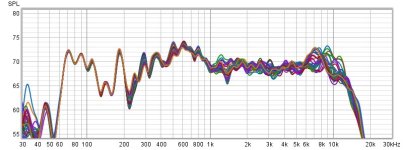
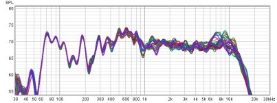
As tripod for the umik I use an old camera tripod, where I can change the vertical position of the mic quite precisely. So yesterday I proceeded to test the response of the system over a vertical displacement of circa 70cm (covering more than the lenght of 2 slims), with a measurement at every 15mm, while my 7-year-old twins were running through the house, but relatively quiet. REW allows 30 measurements per session, so I had to do two, and present two graphs.
This is close to, but not the main listening position (at the listening position there is a bit more bass and less wiggles overall, but our sofa can't be easily moved...). I like that the bass irregularities repeat, so it shows that the mic did stay in place more or less. I think slims1 is the better representation of the measurements, as the tripod was moved less.
Indeed, from circa 1kHz onwards, there is a +-dB variation that could be due to the simulated effects. Maybe it is also because the mic moved a couple mm sidewards (so not only up and down) during the measurements? Looking at the overall wiggles in the measurements, maybe I should worry about other issues first?
What would you do different if you were to measure this?
After this I sat to listen to the new John Surman Album, and I agree with my wife, that sounds much better than sweeeeeeeeeeeeps.
Attachments
I have read a lot of post on vituixcad (by you and wesayso), and that would indeed be an option to study shading options. So many projects, so little time...I can also confirm both theoretically and from listening that combining disappears with distance. Its a simple matter of geometry; but that isn't what I'm talking about. If the CTC is too great for cone drivers or the vertical spacing between membrane boundaries is too great for planar drivers, you don't get a good approximation to a continuous line array whose response would be the same everywhere along the vertical axis. Instead after EQing it to be flat at some height, you would find a very narrow vertical window that remains flat.
You can try long ribbons, if you can find them but even Newform Research ribbons, while good, aren't long enough to completely eliminate this effect.
I think the best practical line array is one done floor to ceiling with small full range drivers and shaded, as exemplified by @wesayso's end result, where he used shading to extend the vertical listening window.
the scale of your graph and the amount of overlay makes for a bit of confusion. You don’t specify your distance from the mic to the array but it’s clear the variations around 8k are room related early reflections.
WRT to overlays, I wanted to show that I did a lot of measurements! 🙂 I am mostly trying to show the min and max range of the frequency response, ie, the max variations when moving my head up and down. But what do you mean with the scale? The dB scale is there at the left, so you must mean another one. I have all the measurements saved, so could redo a plot.
The distance to the arrays is circa 2.5m, the mic was positioned about 1m to the right of the listening position.
The distance to the arrays is circa 2.5m, the mic was positioned about 1m to the right of the listening position.
@nc535 I performed the measurements and could not detect the dips. What do you think happened there, should I measure with vertical steps smaller than 15mm?Now I recall....
About 5 years ago, I did a line array using small full range drivers. As part of that effort, I simulated an array of 16 of these 6816's using Vituix diffraction models. the axial response came out nicely flat but the vertical response was extremely sharp. It would have required vertical "head in a vise" listening. Even 10 degrees off vertical center had several big ( 5db or so) dips. If you look at the ratio of active membrane area to frame area, you will see that the mechanical construction doesn't allow getting units close enough together to approximate a continuous line array
my interest at the time was seated vs standing listening.
you won't see much change with small steps
you will start seeing those big dips if you go seated, +100, +200....+600
I would expect small dips at +/- 100 or 200, but at +600, which for me is standing, big dips
you won't see much change with small steps
you will start seeing those big dips if you go seated, +100, +200....+600
I would expect small dips at +/- 100 or 200, but at +600, which for me is standing, big dips
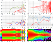
Here is the 6 pack from my Vituix sim. I defined a +/- 10 degree vertical listening window. The green trace in the top left graph shows the variation expected across that window. The lower right graph is the vertical polar map over +/- 90 degrees. You can see that if you stay close to the axis, its nice and flat. Gore more than 5 degrees or so off the vertical axis and it starts falling apart. That is no problem for seated listening but not if you tend to stand up and move around.
Attachments
- Home
- Loudspeakers
- Multi-Way
- Anyone using the GRS PT6816 yet?