I got a couple of these 15 yrs back from eBay .... I now have some time to work on them. Wondering if they are worth it.
Recall them being sold as 80/wpc (8ohms)
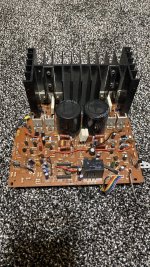
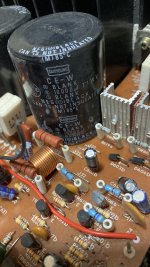
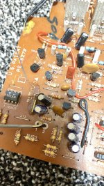
I hooked up some wires and they work, but they have 3 IC’s near the front end, one of which looks like a protection IC that will not allow the relay to engage. I’d prefer to use that circuit, but it might need a separate psu... I cant tell.
Some pics to help identify.
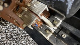
The output’s are c2581/A1106, just a single pair... seems a stretch for 80wpc.... I tested with 63vdc rails and it played all the way till clipping without a mishap....
Recall them being sold as 80/wpc (8ohms)
I hooked up some wires and they work, but they have 3 IC’s near the front end, one of which looks like a protection IC that will not allow the relay to engage. I’d prefer to use that circuit, but it might need a separate psu... I cant tell.
Some pics to help identify.
The output’s are c2581/A1106, just a single pair... seems a stretch for 80wpc.... I tested with 63vdc rails and it played all the way till clipping without a mishap....
Attachments
-
 924499A9-3457-42B1-997E-0C9F69D213CB.jpg931.2 KB · Views: 401
 -
 3B848F46-C962-473A-9424-311517B03CC2.jpg485 KB · Views: 382
 -
 7DCFAFB4-38BD-4388-8343-EE773CE1E75E.jpg524.1 KB · Views: 370
 -
 8CE48009-0EAB-4AE6-9A3F-5349F2425912.jpeg915.8 KB · Views: 368
 -
 2E315720-2F64-4085-A173-520A3D2D5A58.jpg589 KB · Views: 366
Make a list of parts. First of all, transistors and microcircuits.With designations in the (PCB) diagram and types.
The circuit can be reproduced on the board.
c2581 / A1106 140V 10a 20 mHZ - 2x63V=126V
The circuit can be reproduced on the board.
c2581 / A1106 140V 10a 20 mHZ - 2x63V=126V
Last edited:
Worth it?I got a couple of these 15 yrs back from eBay .... I now have some time to work on them. Wondering if they are worth it.
Recall them being sold as 80/wpc (8ohms)
The output’s are c2581/A1106, just a single pair... seems a stretch for 80wpc.... I tested with 63vdc rails and it played all the way till clipping without a mishap....
It seems to work properly.
Is a properly working generic amplifier worth something to YOU?
63V rails is too much since that can produce some 200W into 8 ohm, which 2 lonely devices will NOT handle.
Not with any reliability that is.
Try 45 to 50V DC rails TOPS.
Agreed. I am not overly concerned about the OP stage or the rails, I know how to play with those... its the input/LTP/VAS/Compensation schemes that need to be learnt.
In my experience, its very hard to get 200w with 63v rails. I have modified a Forte Model 3A (200wpc Stock = 74vdc) to use 63v rails, the best I got was 190 watts using a 1.2kva Toroid and 80,000uF per rail. Sorry I digress... the trafo for this kit I used was a small 200va unit and an 8 ohm load. OP devices seemed to handle it without getting warm... I ran it for short bursts... The rails did not stay at 63... must have dipped to 40v or so with the 300 watt bulb I had in series with the PSU...
Back to the topic at hand, Does anyone recognize it ? I have other kit's I'd rather spend time on rather than tracing this kit all the way if I need to do it the hard way...
That´s NO way to *measure* an amplifier, just a safety measure.with the 300 watt bulb I had in series with the PSU
And a 300W bulb is a poor choice: too large to protect, useless to measure.
Try 60/75W. 100W TOPS.
What´s the point of "recognizing" it?
Is it broken and you want to repair it?
I tried a 65watt bulb, it caused oscillations... I have seen this behavior in other amplifiers... dont have a 100w. This was just to avoid catastrophe.... It will however protect the OP devices since it will drop rails much sooner than 300w... filament is analog 🙂. Not full on/ off in this mode. But back to the topic... anyone recognize it? The aim is to use the front end/ vas and put a larger OP stage and maybe bridge it. For that I would like to view a schematic if available easily... which is why it first needs to be identified.
Determine the types of protection microchips and datasheets. Check typical inclusion by tracing.
Some pics to help identify. - This is a printed circuit board with electronic components installed.🙂
Some pics to help identify. - This is a printed circuit board with electronic components installed.🙂
Last edited:
I tried a 65watt bulb, it caused oscillations... I have seen this behavior in other amplifiers... dont have a 100w. This was just to avoid catastrophe.... It will however protect the OP devices since it will drop rails much sooner than 300w... filament is analog 🙂. Not full on/ off in this mode. But back to the topic... anyone recognize it? The aim is to use the front end/ vas and put a larger OP stage and maybe bridge it. For that I would like to view a schematic if available easily... which is why it first needs to be identified.
With that amount of work, indicated i'd rather built a complete amp.
You strugle with unknown frontend and eksperimental output and then want it to bee stable???
In that case the world is not prepeared to pray for you.
Determine the types of protection microchips and datasheets. Check typical inclusion by tracing.
Some pics to help identify. - This is a printed circuit board with electronic components installed.🙂
Great advice, no doubt, but irrelevant to the question asked in the OP.
With that amount of work, indicated i'd rather built a complete amp.
You strugle with unknown frontend and eksperimental output and then want it to bee stable???
In that case the world is not prepeared to pray for you.
Please don't get personal here... I don't need your prayers... If you don't know the answer to the question, just say so.
This forum was a lot user and learning friendly when i joined about 17 years back... now it seems short tempered guys show up to try and belittle others.. maybe makes them feel good. A bit sad.
So you will keep about 10% or less of current amp and build everything else, including enlarged PCBs, transistors, heatsinks, power transformer, filter caps, cabinet, maybe adding a fan.The aim is to use the front end/ vas and put a larger OP stage and maybe bridge it.
You might as well build 100% 🙂 , picking any project you like.
Well documented of course.
I see where you are coming from... but I am more comfortable with all that, vs tinkering with the front end. It seems, I might just put them back in storage... not getting anywhere with this. Might work on a different kit.
Please don't get personal here... I don't need your prayers... If you don't know the answer to the question, just say so.
This forum was a lot user and learning friendly when i joined about 17 years back... now it seems short tempered guys show up to try and belittle others.. maybe makes them feel good. A bit sad.
Hi SIR
This is not personal, its general.
Putting together a unknown front end to a ¨kit" output. Is in general going to bee much more strugling with fitting and adjusting values to make them fit. Then figuring that you still needs the result to bee stable and again inserting and adjusting for stability and margins.
Maybee you think that this is the practical way of learning ?
Id rather say its the hard way. iven recognising the front end adding it to he output is stil giving unknown stray capasitances, causing problems.
Also this front end is built on a single sided pcb thus having por interferens shilding.por groundplane for powersupply, por decopling ground.
So in GENERAL this is the most ekspensive way of learning. and stil not close to developing other than developing to advice listening.
Therfore the warning/advice. I am not alone warning/giving the same advice.
The forum has a lot of treads for different amplifier topologies but that may bee to teoretical or somthing else.
I stil in general wish your fellows god luck
If you have been a diyer for 17 years then you most probably bee able to measure the components values and bee able to draw the schematic for your old school pcb.
Done it 1000 times to service ZERO data "mystery" amplifiers.
Better late at night so Family is asleep, soft background Music, good light and reading glasses , maybe a jeweller´s loupe, pencil, paper and a good eraser (you´ll correct drawing many times) and in an hour or two you may have the full schematic or at least the most important part.
And you are not flying completely blind, you already expect a differential input stage of some kind which will receive feedback, some kind of VAS, high current gain high power output stage, some kind of biasing, and various peripherals not *essential* to circuit function such as short protection, DC detection, turn on delay, which in any case may be interesting to draw too.
Main point being: it´s doable.
Even better: this is hobby/pleasure not a Job with a Boss and timetable, as soon as you feel tired or bored you stop, continue another night (or rainy weekend) when you wish so.
Last edited:
If you have been a diyer for 17 years then you most probably bee able to measure the components values and bee able to draw the schematic for your old school pcb.
Sure... then again if I had the patience, I would not be asking of anyone recognized the board... Thanks for your help anyway in stating the obvious.
- Home
- Amplifiers
- Solid State
- Anyone recognize this old amplifier Kit?