I have seen some people try the TC9 in horns (xrk in the tractrix synergy, weltersys on maltese horn), but how about in a waveguide?
Let's say I want to build a FAST setup with (preferably close to constant) directivity to below 1000 Hz, then a waveguide on a 3-4" fullrange driver should be a good start, no?
/Anton
Let's say I want to build a FAST setup with (preferably close to constant) directivity to below 1000 Hz, then a waveguide on a 3-4" fullrange driver should be a good start, no?
/Anton
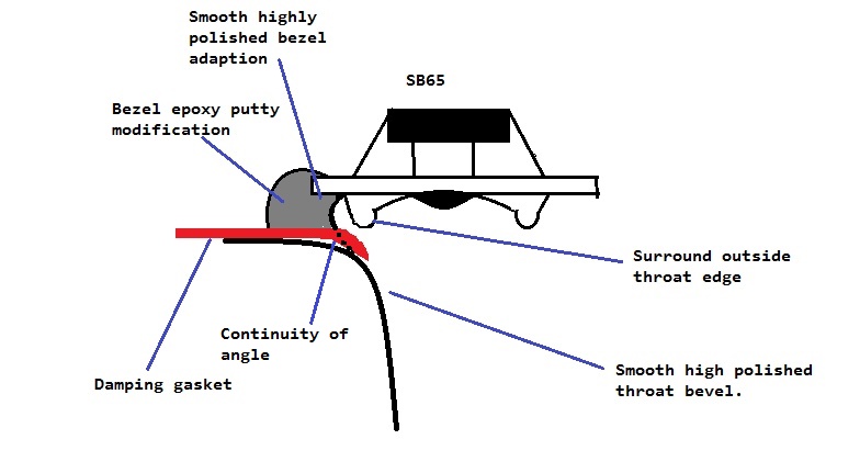
Please design one for us! 😀 The trick is to make the edge transition from driver bezel/surround to the WG so smooth that it doesn't cause the almost-certain-to-have dips at the driver-radius to WG wall half-wave frequency. The Bookshelf point source horn thread has some nice tricks that really helped the SB65WBAC-25 driver to put out a smooth output.
I would like to have a WG that is maybe 75mm (bezel to baffle) deep to allow me to get perfect time alignment when used with a woofer in a FAST with 1st order XO.
Note that TC9FD and 10F/84xx have the same bolt circle radius for mounting (shows they have same Danish DNA). The TC9 has a square bezel and 10F a round bezel. The WG itself would be identical, just the shape of the bezel frame is different. TC9 has bonus that it coems with a gasket foam on the front face already attached.
Now, I really need to fix the busted 3d printer... 🙂
Last edited:
Since a 3.5" fullrange driver differs quite significantly from other things you usually put in a waveguide I'm guessing that there needs to be a lot of trial and error with prototypes to get rid of peaks and dips. Or, as my approach usually is, trying to simulate the response.
I started with measuring the TC9 with calipers and making a FEM model. First a sim of it being mounted (countersunk) on an infinite baffle:

Compared to data in datasheet:
First cone resonance at 9 kHz I'm guessing when comparing to simulated response (pistonic).
Here is Weltersys polars for the TC9:
The directional behavior is overall correctly predicted by the simulation.
Here is SPL for the first 1 m at 1 kHz:

Monopole behavior.
At 4 kHz:

Starting to beam slightly.
At 8 kHz:

More beaming and slight lobing.
At 16 kHz:

Beaming and lobing. Here is a close-up:

You can se the shape of the cone.
I'm assuming pistonic motion (constant acceleration, linearly declining over surround).
I've started iterating a little to see what kind of waveguide could suit this driver. A question: is the cone of the 10F identical in shape? I'm guessing it is better suited for loading in a waveguide since the cone should be significantly stiffer with the added fiberglass.
/Anton
I started with measuring the TC9 with calipers and making a FEM model. First a sim of it being mounted (countersunk) on an infinite baffle:
Compared to data in datasheet:
An externally hosted image should be here but it was not working when we last tested it.
First cone resonance at 9 kHz I'm guessing when comparing to simulated response (pistonic).
Here is Weltersys polars for the TC9:
The directional behavior is overall correctly predicted by the simulation.
Here is SPL for the first 1 m at 1 kHz:
Monopole behavior.
At 4 kHz:
Starting to beam slightly.
At 8 kHz:
More beaming and slight lobing.
At 16 kHz:
Beaming and lobing. Here is a close-up:
You can se the shape of the cone.
I'm assuming pistonic motion (constant acceleration, linearly declining over surround).
I've started iterating a little to see what kind of waveguide could suit this driver. A question: is the cone of the 10F identical in shape? I'm guessing it is better suited for loading in a waveguide since the cone should be significantly stiffer with the added fiberglass.
/Anton
Visually, the TC9 and 10F cone profile are very similar. Rounded dust cap in middle. Profile of cone is mostly conical, might be a bit curved. I can take some caliper measurements later when I get back to the lab. All you can do is assume pistonic for first cut. Make throat same dia as middle of surround roll and allow a smooth curved undercut below surround to bezel edge, Probably put dampening felt in that crevice. Here is the profile Bushemeister came up with after much trial-and-error:
http://www.diyaudio.com/forums/multi-way/285030-bookshelf-multi-source-horn-125.html#post4644522
http://www.diyaudio.com/forums/multi-way/285030-bookshelf-multi-source-horn-125.html#post4644522
That's the plan! 😉xrk971 said:Please design one for us!
Thanks for the guidance, I've read that earlier as well.Visually, the TC9 and 10F cone profile are very similar. Rounded dust cap in middle. Profile of cone is mostly conical, might be a bit curved. I can take some caliper measurements later when I get back to the lab. All you can do is assume pistonic for first cut. Make throat same dia as middle of surround roll and allow a smooth curved undercut below surround to bezel edge, Probably put dampening felt in that crevice. Here is the profile Bushemeister came up with after much trial-and-error:
http://www.diyaudio.com/forums/multi-way/285030-bookshelf-multi-source-horn-125.html#post4644522
Let's start with a few iterations (all 7.5 cm deep):
Iteration 1 - How about a simple conical that fits around the surround
Easiest to make. Here a 90 degree WG:

Response:

Quite decent 30-60 deg, but not so much 0-15 deg.
How about a 120 degree WG:

Response:

Nah, not better.
Iteration 2 - Conical above the surround
Alright, so let's follow xrks advice about starting the WG at top of surround (with a distance of 3.5 mm for excursion). The throat is 70 mm diameter.

Response:

Not really better than the 90 degree above.
Iteration 3 - Added initial roundover

Response:

That's a little better, decreased the on-axis dip 🙂 The radius is 2 cm.
/Anton
Nice work Onni. I think a radius on the mouth edge will help as well. And instead of conical, make it expand a little faster on second half of expansion with a curved shape. Still for 75mm depth and similar angle of coverage. One way to approximate is apply a large radius round over tangent to angle of cone at 50% depth and tangent to baffle at exit. Use a single spline and tweak by hand. Then do swept revolution, like this:
Attachments
Last edited:
Thanks for the effort, subscribed!🙂
ps. practical waveguide design tips/math by Rod Elliot Practical DIY Waveguides - Part 1
ps. practical waveguide design tips/math by Rod Elliot Practical DIY Waveguides - Part 1
Interesting read! The method is however mainly applicable to dome tweeters, for fullrange drivers there needs to be a transition from cone to conical section. I'm guessing that it is difficult to calculate this analytically as the cone profile is quite complex, but iterating using software should be possible 🙂 I've got better results than shown already, I'll post them later.Thanks for the effort, subscribed!🙂
ps. practical waveguide design tips/math by Rod Elliot Practical DIY Waveguides - Part 1
/Anton
yeah Rod has some good articles that are somewhat scientific with literature references and all 🙂
Finnish pro audio company AuraAudio has speaker model F1 with interesting waveguide for inspiration
Aura Audio - Aura Audio F1 - F-Pro Esitystekniikka
Large picture http://www.auraaudio.fi/pics/F1.jpg
I'm guessing they have highly optimized waveguide for their application. It seems to have a bezel. And some weird wavy surface on the sides. Cool, must be computers crunching data to aid with design.
Last edited:
Array gives vertical control and wave-guide gives horizontal control.Finnish pro audio company AuraAudio has speaker model F1 with interesting waveguide for inspiration
Wouldn't it be easier to put a small line array of 3 or 4 drivers vertically and put straight walls on the sides ie a waveguide only horizontally?
Last edited:
Maybe the waveguide reduces lobing? I have seen that approach.Array gives vertical control and wave-guide gives horizontal control.
Wouldn't it be easier to put a small line array of 3 or 4 drivers vertically and put straight walls on the sides ie a waveguide only horizontally?
/Anton
sorry i didn't mean to point discussion to line array design. I just tried to give a hint for successfull waveguide design for FR driver since the Rod Elliot article I posted earlier was for dome tweeter which the tc9 is not.
Just for reference, here is a TB 2" driver in a waveguide. Martinsson's Blog - 2" fullrange TB W2803SE on JBL 2386 upgrade.
This has back open, kinda dipole-ish, it may not work with a smaller wave-guide.
This has back open, kinda dipole-ish, it may not work with a smaller wave-guide.
Last edited:
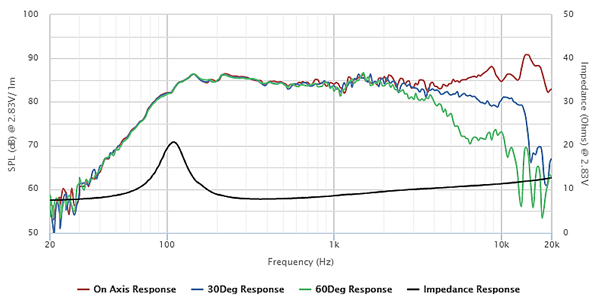
That is quite impressive and affordable! Is that without EQ? Might be suitable for Harsch XO that requires a large offset?If we are allowing big WG’s and 2.5in drivers here is SB65WB in LTH142 that I measured:
Here are some more results for the TC9:
Iteration 4
I tried going for the smoothest possible profile, so it starts around the surround and is a quadratic curve (2nd degree). There is a guide point 40 mm from the driver bezel and on the centerline.


Quite smooth! Not very constant directivity though. More like a tractrix maybe?
Iteration 5 - more conical
Let's try moving the guide point down slightly (10 mm) to get a more conical profile (and hopefully more constant directivity).


Now that's not so bad 🙂
Note: The downward tilt is exaggerated by assuming a pistonic motion with constant acceleration. As the waveguide causes the driver to couple better to the air it will cause the moving mass to increase and therefore the acceleration.
/Anton
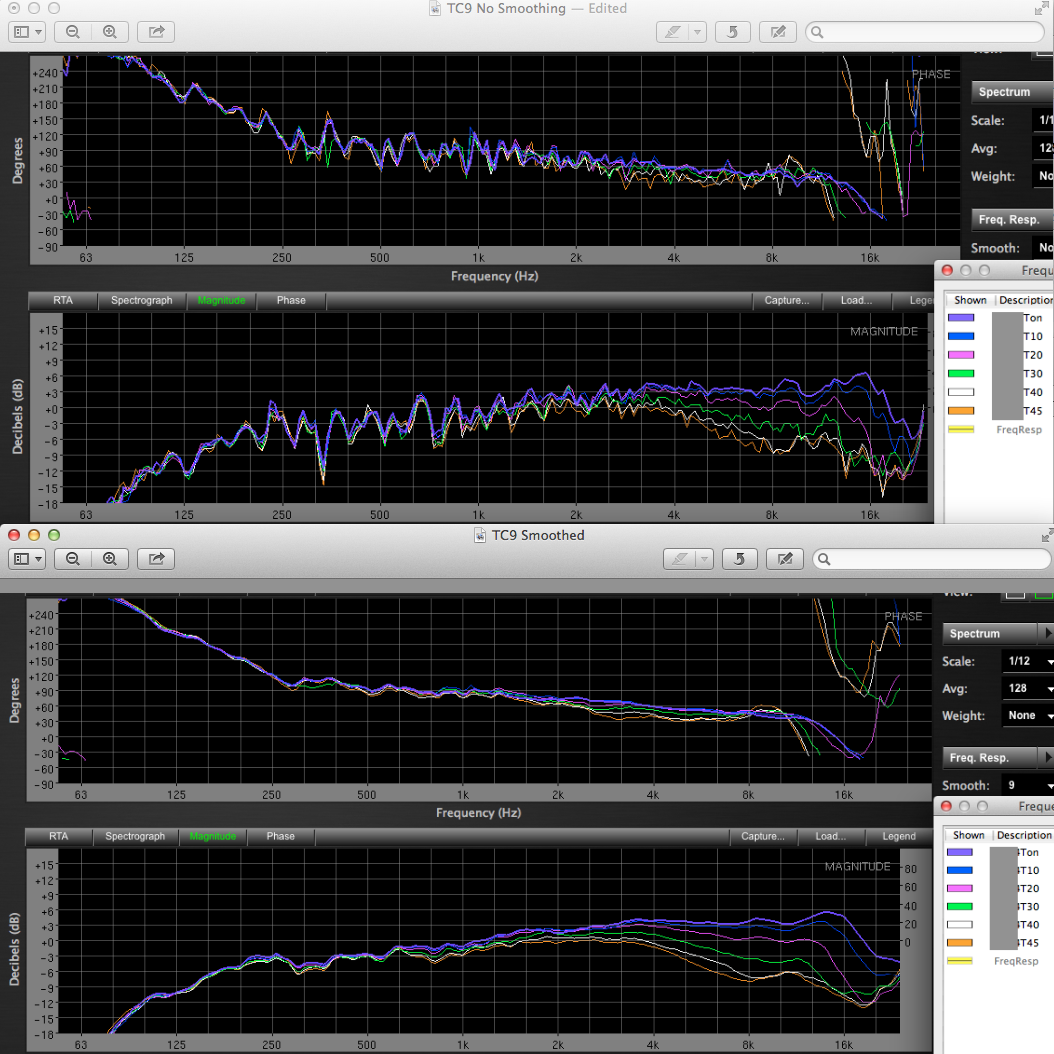
No, it is with PEQ applied. Although I recall Kees was able to get a super flat response on a tractrix and FR8S using a simple 10uF high pass cap. It was kind of unbelievably good and that is what I would aim for if I were to do it again and avoid all this DSP stuff. If you look at raw, it is a -6dB/oct fall off, so a high pass cap at +6dB/oct rise, if picked correctly, can null that.
Here is comparison of raw vs with PEQ:
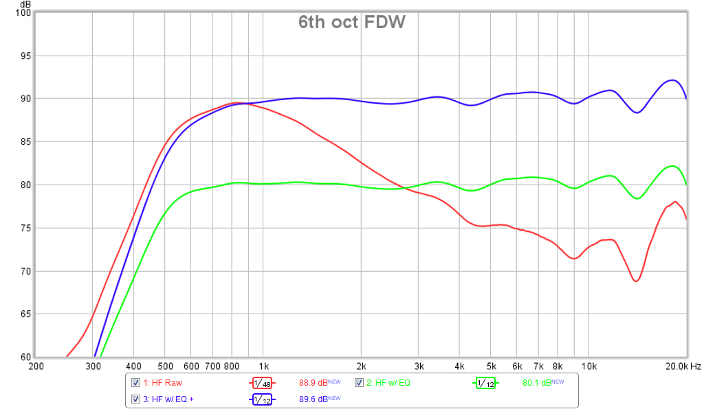
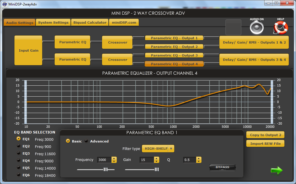
Here is the PEQ applied:
Result with Phase:
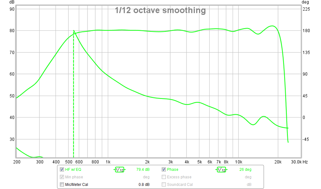
More here:
A Bookshelf Multi-Way Point-Source Horn
Here is comparison of raw vs with PEQ:
Here is the PEQ applied:
Result with Phase:
More here:
A Bookshelf Multi-Way Point-Source Horn
Last edited:
Ah, right. Would be interesting to see response with just a single capacitor (and maybe a parallel resistor to increase effectiveness of said capacitor at resonance).
Iteration 6
A slightly deeper WG (12 cm).


This is IMO decent. I might test this geometry... I'll try a few more iterations to see if I can get the on-axis response a little smoother (dip at 5.5 kHz), but off axis is already acceptable.
If I add a 50 mm fillet (roundover) at the mouth I get this:


Overall a little smoother, but no huge difference.
/Anton
Iteration 6
A slightly deeper WG (12 cm).
This is IMO decent. I might test this geometry... I'll try a few more iterations to see if I can get the on-axis response a little smoother (dip at 5.5 kHz), but off axis is already acceptable.
If I add a 50 mm fillet (roundover) at the mouth I get this:
Overall a little smoother, but no huge difference.
/Anton
Last edited by a moderator:
A few more figures for the last WG:
SPL at 1 kHz:

Slightly directional.
At 2 kHz:

Distincly directional.
At 4 kHz:

At 8 kHz:

Still no lobing.
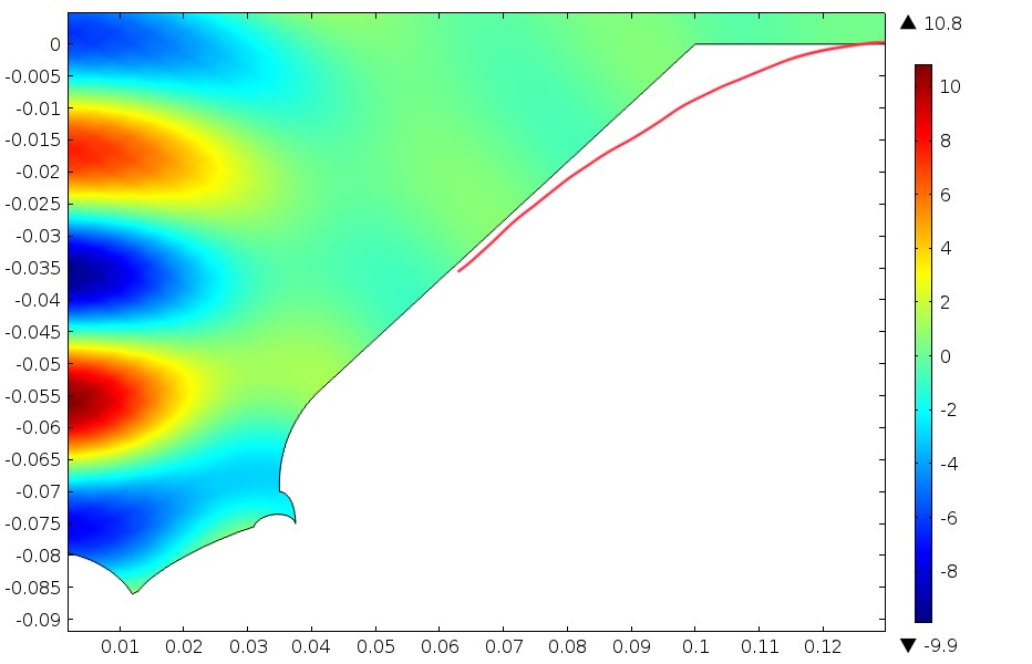
At 16 kHz:

Lobing, but smoother than mounted on flat baffle (compare to post 4).
Animation of pressure distribution at 4 kHz:

And at 8 kHz:

Smooth.
At 16 kHz:

Lobing present (0 pressure along line).
EDIT: I can't get the animations to play :/
/Anton
SPL at 1 kHz:
Slightly directional.
At 2 kHz:
Distincly directional.
At 4 kHz:
At 8 kHz:
Still no lobing.
At 16 kHz:
Lobing, but smoother than mounted on flat baffle (compare to post 4).
Animation of pressure distribution at 4 kHz:
And at 8 kHz:
Smooth.
At 16 kHz:
Lobing present (0 pressure along line).
EDIT: I can't get the animations to play :/
/Anton
Last edited:
- Home
- Loudspeakers
- Full Range
- Anyone made a waveguide for the TC9 (or 10F)?