Just an idea. Non cross coupled. You can keep your CCS on the cathode. It may be a good idea to go the direct coupled route. The drivers would probably appreciate the extra voltage.
An externally hosted image should be here but it was not working when we last tested it.
Shoog,
I don't believe the circuit you posted in post #25 will work at all.
You have CCS's in series with the OPT windings - to me that means the current through the OPT cannot change, which means no transformer action and hence no output power.
Or looking at it in another way, the cathodes will move up & down in voltage, but the impedance of the CCS's will be orders of magnitude higher than that of the OPT winding, so there will be no voltage chage across the OPTs, and hence no current change = no output power.
You can connect the bottoms of the OPTs together and have one CCS, that will work but then you are held to rigorous Class A1 operation.
Regards, Allen (Vacuum State)
Jeb-D. said:Just an idea. Non cross coupled. You can keep your CCS on the cathode. It may be a good idea to go the direct coupled route. The drivers would probably appreciate the extra voltage.
An externally hosted image should be here but it was not working when we last tested it.
This time ultralinear drivers have shorter feedback signal path than before (through transformers). But you still have to think a bit better about how to take signal from it's output and feed your speaker.
But you still have to think a bit better about how to take signal from it's output and feed your speaker.
Not sure I understand.
Do you mean feed the screen?
Perhaps replacing the screen capacitors with voltage regulators? I was considering that, but not until after posting the drawing.
Jeb-D. said:
Not sure I understand.
Do you mean feed the screen?
Perhaps replacing the screen capacitors with voltage regulators? I was considering that, but not until after posting the drawing.
No, I mean the same what Allen Wright said about Shoog's schematic. You've loaded cathodes by current sources on DC, now you need to load them on AC, through an output transformer to the speaker. You may connect your transformer directly between cathodes, but make sure the CCS' provide currents to pull equal voltages on cathodes, otherwise the transformer will be DC biased.
My bad. I forgot the caps. Here was the intention.
If the transformer were placed between the two CCS, voltage imbalance would be difficult to overcome (as you pointed out already). Also, for that to work,the CCS's would have to be left unbypassed. It would operate like parallel feed, which wouldn't allow the cathode to swing below ground potential.
The configuration above, could be used as fixed or cathode biased (or any mix between). Also allow the cathode to swing below ground potential.
An externally hosted image should be here but it was not working when we last tested it.
If the transformer were placed between the two CCS, voltage imbalance would be difficult to overcome (as you pointed out already). Also, for that to work,the CCS's would have to be left unbypassed. It would operate like parallel feed, which wouldn't allow the cathode to swing below ground potential.
The configuration above, could be used as fixed or cathode biased (or any mix between). Also allow the cathode to swing below ground potential.
You can use one cap only (parafeed between cathodes) However, no swing below ground potential though...
Thanks for the input.
I am going to work up a schematic having the CCS's in the anodes. I was thinking about the concept and I am fairly certain that if implemented with an input transformer and direct coupling between stages with cross coupled feedback - it should be both DC and AC compensating. Both the anode voltages will shift to maintain DC balance, but also the plates of the pentode will shift to adjust the bias on the outputs. This should be quite rigerous and stable with minimum wasted power.
When I have lashed up a proposal I would appreciate your thoughts on confirming its viability.
Shoog
What on earth is the point of having CCS's in the anodes of a CF output stage?
Regards, Allen (Vacuum State)
Regards, Allen (Vacuum State)
Allen is Wright (I'm sorry, couldn't resist), whether the CCS's are on the plate or cathode. If they aren't AC bypassed, it's not going to allow any AC voltage to develop across the load.
You could use the CCS's on the plate for DC balance. But you would need a cap either across the CCS, or from the plate to ground.
You could use the CCS's on the plate for DC balance. But you would need a cap either across the CCS, or from the plate to ground.
Its the same principle as having a CCS anode load in a preamp stage, maximum mu and linearity from the triode. In this case it is there simply to generate a signal to feedback - and most importantly to create DC balance in the output transformer.
Or is this faulty thinking?
Isn't this essentially the technique used in the Current source Zens but with the output from a different place.
Shoog
Or is this faulty thinking?
Isn't this essentially the technique used in the Current source Zens but with the output from a different place.
Shoog
>>Its the same principle as having a CCS anode load in a preamp stage, maximum mu and linearity from the triode.<<
If the stage was a common cathode stage, yes. But not for a cathode follower stage. There is has minimal to zero relevance.
> In this case it is there simply to generate a signal to feedback - and most importantly to create DC balance in the output transformer. <<
It won't create DC balance, as to get control of the currents in a tube you need to control the grid/cathode voltage, changing the anode V is a second or even third order change, and far less effective.
Regards, Allen (Vacuum State)
I was thinking about this in bed last night.
A cathode follower needs a bypass to develop the signal and in most preamplifier instances the load is the bypass. So in order to keep DC imbalance out of the transformer, it needs to bypass the cathode load and needs a cap as in parafeed outputs.
I will ponder.
Allen whilst you are here - what is the current demand of the phono stage of your FVP5. I have just built a version of the line stage with ECF80's and have a bit of spare case space so was thinking of adding the phono stage if the current demand is modest.
Shoog
You may want to consider a variant of the topology in post #46. The local screen feedback will make the driver run in Ultra-linear, except the output tube will be in the loop (which means lower Zout). The screens could be direct coupled to the output's cathode if you had a -V power supply for the driver.
Also, bypassing the CCS's and leaving the the OPT in standard config(DC current through the windings) as in post #46 will have several advantages over parallel feed.
BTW, I was simulating a 6as7 cathode follower the other day. It takes a peak drive voltage about equal to 2x Vgk of the output tube. Of course it does vary depending on the load impedance chosen. For the driver, you're probably going to need either a -V power supply rail, or a separate higher B+.
I was wondering how far you could push DC voltage feedback for stabilization of the output operating point. In order to see this I would need to learn how to run a simulator - which I haven't got time for at the moment.
I really don't want the parafeed arrangement - I would go so far as to say that the amp wouldn't be worth implementing if I went down that path.
Shoog
I really don't want the parafeed arrangement - I would go so far as to say that the amp wouldn't be worth implementing if I went down that path.
Shoog
Shoog,
The FVP-5A needs up to 15mA per channel for the phono section. That's in the MC setting, less in the MM setting.
It must have a Super Reg or it's just not my design, no matter how well you do a passive filter.
Why and how did you use ECF's in an all triode circuit?
Regards, Allen (Vacuum State)
The FVP-5A needs up to 15mA per channel for the phono section. That's in the MC setting, less in the MM setting.
It must have a Super Reg or it's just not my design, no matter how well you do a passive filter.
Why and how did you use ECF's in an all triode circuit?
Regards, Allen (Vacuum State)
I used a the triode as the front end running at -8V bias and about 7mA current. This works really well as it has mu of 14 which gives me much more volume flexability than the ECC88.
I used the partnered pentode with elevated cathode as the current source on the bottom with a separate reference string and the screen fed from a IRF720.
I used the other triode as the cathode follower, and the partnered pentode is triode strapped as the constant voltage element.
The SLCF is running at about 10mA.
I am just running a passive power supply.
I just got it finished. I had previously run a version using ECC88's and a IRF710 as the constant voltage element. I was surprised at the leap up in detail and dynamics which had come with the upgrade, very full ricjh and detailed sound with great clarity.
Shoog
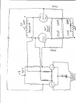
Jed,
I was reading your thread on the Thermatrak transistor and it gave me inspiration for the attached schematic.
By using the Garter bias the voltage and current should be matched at the 6080 cathodes - problem solved !! I still wanted the cross coupled feedback so I decided that instead of using voltage followers on the anodes why not use inductors.This prevents voltage wastage. Since the most readily available inductors are output transformers there is a spare secondary winding going to waste, so why not use it for a bit of cathode feedback.
So the design has degenerative cathode feedback, crosscoupled feedback and a bit of cathode feedback.
Penny for your thoughts.
Shoog
Edit I just noticed that i missed a coupling cap. Unfortunately direct coupling would make the circuit a bit unpredictable.
Attachments
>Penny for your thoughts.<
KISS rules, and that's far from KISS...
Regards, Allen (Vacuum State)
KISS rules, and that's far from KISS...
Regards, Allen (Vacuum State)
The nice thing is that it would be relatively easy to do a bench mock up and switch in and out all the various elements of feedback and see which sounds best. You could easily try it as a simple anode follower and then compare it to the cathode foillower. Switch in the cathode feeddback - see what it sounds like. All very easy to suck it and see - which is what I like.
The main thing is that it seems to be a way to get DC balanced without the voltage offset - which is what I was looking for and I know from experiance that Garter bias works a treat.
Shoog
The main thing is that it seems to be a way to get DC balanced without the voltage offset - which is what I was looking for and I know from experiance that Garter bias works a treat.
Shoog
- Status
- Not open for further replies.
- Home
- Amplifiers
- Tubes / Valves
- Anyone know of a dual pentode suitable for a LTP.